LKA/LDA SYSTEM, Diagnostic DTC:U0235, U1104
| DTC Code | DTC Name |
|---|---|
| U0235 | Lost Communication with Cruise Control Front Distance Range Sensor |
| U1104 | Lost Communication with Driving Support ECU |
DESCRIPTION
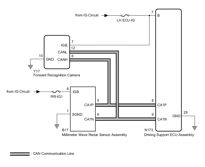
The forward recognition camera communicates with the driving support ECU assembly and millimeter wave radar sensor assembly via CAN communication. If there is a communication error with the driving support ECU assembly or millimeter wave radar sensor assembly, the forward recognition camera stores DTC U0235 or U1104.
| DTC No. | DTC Detection Condition | Trouble Area |
|---|---|---|
| U0235 | 2 seconds after the power switch is turned on (IG), a communication error between the millimeter wave radar sensor assembly and the forward recognition camera is detected for approximately 5 seconds |
|
| U1104 | 2 seconds after the power switch is turned on (IG), a communication error between the driving support ECU assembly and the forward recognition camera is detected for approximately 5 seconds |
|
WIRING DIAGRAM
CAUTION / NOTICE / HINT
Note
-
Inspect the fuses for circuits related to this system before performing the following procedure.
-
When disconnecting the cable from the negative (-) auxiliary battery terminal, some systems need to be initialized after the cable is reconnected Click here.
-
When replacing the driving support ECU assembly, always replace it with a new one. If a driving support ECU assembly which was installed to another vehicle is used, the information stored in the driving support ECU assembly will not match the information from the vehicle. As a result, a DTC may be stored.
-
If the forward recognition camera has been replaced with a new one, be sure to perform forward recognition camera learning Click here.
-
When the millimeter wave radar sensor assembly is replaced with a new one, adjustment of the radar sensor beam axis must be performed Click here.
PROCEDURE
-
READ VALUE USING GTS (CAN BUS CHECK)
-
Connect the GTS to the DLC3.
-
Turn the power switch on (IG).
-
Turn the GTS on.
-
Enter the following menus: System Select / Can Bus Check.
-
for LHD: Click here
-
for RHD: Click here
Result Result Proceed to All of the ECUs and sensors that are currently connected to the CAN communication system are displayed A None of the ECUs and sensors that are currently connected to the CAN communication system are displayed, or some of them are not displayed (for LHD) B None of the ECUs and sensors that are currently connected to the CAN communication system are displayed, or some of them are not displayed (for RHD) C -
B 
GO TO CAN COMMUNICATION SYSTEM Click here
C
GO TO CAN COMMUNICATION SYSTEM Click here
A 
-
-
CHECK DTC OUTPUT (PRE-CRASH SAFETY SYSTEM)
Tech Tips
When pre-crash safety system DTC U1002 is output, check that the local bus is functioning normally by performing the diagnosis procedure for U1002.
-
Check for DTCs Click here.
Result Result Proceed to DTC U1002 is not output A DTC U1002 is output B
B
GO TO PRE-CRASH SAFETY SYSTEM Click here
A
-
-
CHECK FOR SHORT IN SUB BUS LINE
-
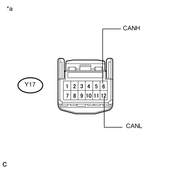
Text in Illustration *a Front view of wire harness connector
(to Forward Recognition Camera)
Disconnect the forward recognition camera connector.
-
Measure the resistance according to the value(s) in the table below.
Standard Resistance Tester Connection Condition Specified Condition Y17-6 (CANH) - Y17-12 (CANL) Cable disconnected from negative (-) auxiliary battery terminal 108 to 132 Ω
NG
REPAIR OR REPLACE HARNESS OR CONNECTOR (CAN BUS LINE)
OK
-
-
CHECK DTC OUTPUT (LKA/LDA SYSTEM)
-
Check for DTCs Click here.
Result Result Proceed to DTC U0235 and U1104 are output A Only DTC U1104 is output B Only DTC U0235 is output C
B 
CHECK POWER SOURCE CIRCUIT (DRIVING SUPPORT ECU ASSEMBLY) Click here
C
CHECK POWER SOURCE CIRCUIT (MILLIMETER WAVE RADAR SENSOR ASSEMBLY) Click here
A
-
-
CHECK POWER SOURCE CIRCUIT (DRIVING SUPPORT ECU ASSEMBLY)
-
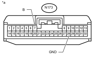
Text in Illustration *a Front view of wire harness connector
(to Driving Support ECU Assembly)
Disconnect the driving support ECU assembly connector.
-
Measure the voltage according to the value(s) in the table below.
Standard Voltage Tester Connection Condition Specified Condition N173-7 (B) - Body ground Power switch on (IG) 11 to 14 V -
Measure the resistance according to the value(s) in the table below.
Standard Resistance Tester Connection Condition Specified Condition N173-28 (GND) - Body ground Always Below 1 Ω
NG
REPAIR OR REPLACE HARNESS OR CONNECTOR (POWER SOURCE CIRCUIT)
OK
-
-
CHECK POWER SOURCE CIRCUIT (MILLIMETER WAVE RADAR SENSOR ASSEMBLY)
-
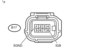
Text in Illustration *a Front view of wire harness connector
(to Millimeter Wave Radar Sensor Assembly)
Disconnect the millimeter wave radar sensor assembly connector.
-
Measure the voltage according to the value(s) in the table below.
Standard Voltage Tester Connection Condition Specified Condition B17-8 (IGB) - Body ground Power switch on (IG) 11 to 14 V -
Measure the resistance according to the value(s) in the table below.
Standard Resistance Tester Connection Condition Specified Condition B17-1 (SGND) - Body ground Always Below 1 Ω
OK
REPLACE FORWARD RECOGNITION CAMERA Click here
NG
REPAIR OR REPLACE HARNESS OR CONNECTOR (POWER SOURCE CIRCUIT)
-
-
CHECK POWER SOURCE CIRCUIT (DRIVING SUPPORT ECU ASSEMBLY)
-
Text in Illustration *a Front view of wire harness connector
(to Driving Support ECU Assembly)
Disconnect the driving support ECU assembly connector.
-
Measure the voltage according to the value(s) in the table below.
Standard Voltage Tester Connection Condition Specified Condition N173-7 (B) - Body ground Power switch on (IG) 11 to 14 V -
Measure the resistance according to the value(s) in the table below.
Standard Resistance Tester Connection Condition Specified Condition N173-28 (GND) - Body ground Always Below 1 Ω
NG
REPAIR OR REPLACE HARNESS OR CONNECTOR (POWER SOURCE CIRCUIT)
OK
-
-
REPLACE DRIVING SUPPORT ECU ASSEMBLY
-
Replace the driving support ECU assembly Click here.
NEXT
-
-
CHECK DTC OUTPUT (LKA/LDA SYSTEM)
-
Clear the DTCs Click here.
-
Make sure that the DTC detection conditions are met.
Tech Tips
If the detection conditions are not met, the system cannot detect the malfunction.
-
Turn the power switch on (IG) and wait 7 seconds or more.
-
-
Check for DTCs Click here.
Result Result Proceed to DTC U1104 is not output A DTC U1104 is output B
A
END (DRIVING SUPPORT ECU ASSEMBLY WAS DEFECTIVE)
B
REPLACE FORWARD RECOGNITION CAMERA Click here
-
-
CHECK POWER SOURCE CIRCUIT (MILLIMETER WAVE RADAR SENSOR ASSEMBLY)
-
Text in Illustration *a Front view of wire harness connector
(to Millimeter Wave Radar Sensor Assembly)
Disconnect the millimeter wave radar sensor assembly connector.
-
Measure the voltage according to the value(s) in the table below.
Standard Voltage Tester Connection Condition Specified Condition B17-8 (IGB) - Body ground Power switch on (IG) 11 to 14 V -
Measure the resistance according to the value(s) in the table below.
Standard Resistance Tester Connection Condition Specified Condition B17-1 (SGND) - Body ground Always Below 1 Ω
NG
REPAIR OR REPLACE HARNESS OR CONNECTOR (POWER SOURCE CIRCUIT)
OK
-
-
REPLACE MILLIMETER WAVE RADAR SENSOR ASSEMBLY
-
Replace the millimeter wave radar sensor assembly Click here.
-
Adjust the millimeter wave radar sensor assembly Click here.
NEXT
-
-
CHECK DTC OUTPUT (LKA/LDA SYSTEM)
-
Clear the DTCs Click here.
-
Make sure that the DTC detection conditions are met.
Tech Tips
If the detection conditions are not met, the system cannot detect the malfunction.
-
Turn the power switch on (IG) and wait 7 seconds or more.
-
-
Check for DTCs Click here.
Result Result Proceed to DTC U0235 is not output A DTC U0235 is output B
A
END (MILLIMETER WAVE RADAR SENSOR ASSEMBLY WAS DEFECTIVE)
B
REPLACE FORWARD RECOGNITION CAMERA Click here
-