DYNAMIC RADAR CRUISE CONTROL SYSTEM, Diagnostic DTC:C1A05
| DTC Code | DTC Name |
|---|---|
| C1A05 | Stop Light Switch Circuit |
DESCRIPTION
When the brake pedal is depressed, the stop light switch assembly sends a brake pedal operation signal to the driving support ECU assembly. After reception of this signal, the driving support ECU assembly cancels the dynamic radar cruise control system. When the driving support ECU assembly detects a problem in the stop light switch assembly circuit, DTC C1A05 is stored.
| DTC Code | DTC Detection Condition | Trouble Area |
|---|---|---|
| C1A05 | When the power switch is on (IG) and cruise control switch is on, the driving support ECU assembly detects a malfunction in the signal from stop light switch assembly circuit. |
|
WIRING DIAGRAM
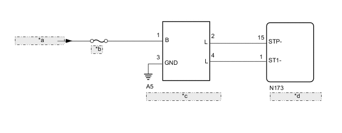
| *a | from Auxiliary Battery |
| *b | STOP |
| *c | Stop Light Switch Assembly |
| *d | Driving Support ECU Assembly |
CAUTION / NOTICE / HINT
Note
-
Inspect the fuses for circuits related to this system before performing the following inspection procedure.
-
When replacing the driving support ECU assembly, always replace it with a new one. If a driving support ECU assembly which was installed to another vehicle is used, the information stored in the driving support ECU assembly will not match the information from the vehicle. As a result, a DTC may be stored.
PROCEDURE
-
CHECK HARNESS AND CONNECTOR (STOP LIGHT SWITCH ASSEMBLY - BATTERY AND BODYGROUND)
-
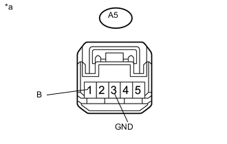
Text in Illustration *a Front view of wire harness connector
(to Stop Light Switch Assembly)
Disconnect the stop light switch assembly connector.
-
Measure the resistance according to the value(s) in the table below.
Standard Resistance Tester Connection Condition Specified Condition A5-3 (GND) - Body ground Always Below 1 Ω -
Measure the voltage according to the value(s) in the table below.
Standard Voltage Tester Connection Condition Specified Condition A5-1 (B) - Body ground Always 11 to 14 V
NG 
REPAIR OR REPLACE HARNESS AND CONNECTOR
OK 
-
-
CHECK HARNESS AND CONNECTOR (DRIVING SUPPORT ECU ASSEMBLY - STOP LIGHT SWITCH ASSEMBLY)
-
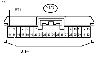
Text in Illustration *a Front view of wire harness connector
(to Driving Support ECU Assembly)
Disconnect the driving support ECU assembly connector.
-
Measure the voltage according to the value(s) in the table below.
Standard Voltage Tester Connection Condition Specified Condition N173-1 (ST1-) - Body ground Power switch on (IG), brake pedal released 7.5 to 14 V Power switch on (IG), brake pedal depressed 0 to 1.5 V N173-15 (STP-) - Body ground Brake pedal released 0 to 1.5 V Brake pedal depressed 7.5 to 14 V
NG
REPAIR OR REPLACE HARNESS AND CONNECTOR
OK
-
-
CHECK STOP LIGHT SWITCH ASSEMBLY
-
Temporarily replace the stop light switch assembly with a new or normally functioning one Click here.
-
Clear the DTCs Click here.
-
Make sure that the DTC detection conditions are met.
Tech Tips
If the following procedure is not performed, the previously output DTC cannot be detected.
-
Turn the power switch on (IG).
-
Turn the cruise control system on using the cruise control main switch (ON/OFF).
-
Depress the brake pedal.
-
-
Check for DTCs Click here.
Result Result Proceed to DTC C1A05 is not output A DTC C1A05 is output B
A
END (STOP LIGHT SWITCH ASSEMBLY IS DEFECTIVE)
B
REPLACE STOP LIGHT SWITCH ASSEMBLY
-