DYNAMIC RADAR CRUISE CONTROL SYSTEM TERMINALS OF ECU
-
CHECK POWER MANAGEMENT CONTROL ECU
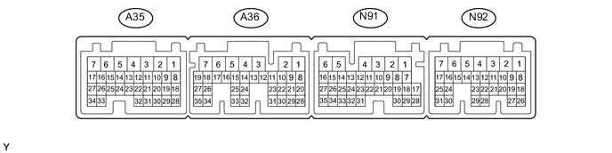
Terminal No. (Symbol) Wiring Color Terminal Description Condition Specified Condition A36-10 (D) - N91-6 (E1) L - W-B Shift lever position signal Power switch on (IG), shift lever in D 11 to 14 V Power switch on (IG), shift lever not in D 0 to 1.5 V N92-20 (SFTD) - N91-6 (E1) W - W-B Transmission control Power switch on (IG), shift lever in S position 11 to 14 V Power switch on (IG), shift lever in (-) 0 to 1.5 V N92-21 (SFTU) - N91-6 (E1) Y - W-B Transmission control Power switch on (IG), shift lever in S position 11 to 14 V Power switch on (IG), shift lever in (+) 0 to 1.5 V N92-22 (M) - N91-6 (E1) R - W-B Transmission control Power switch on (IG), shift lever in S position 11 to 14 V Power switch on (IG), shift lever not in S position 0 to 1.5 V -
CHECK DRIVING SUPPORT ECU ASSEMBLY

Terminal No. (Symbol) Wiring Color Terminal Description Condition Specified Condition N173-3 (BZ) - N173-28 (GND) P - BR*1
P - W-B*2
Skid control buzzer assembly output Power switch on (IG), skid control buzzer assembly not sounding 11 to 14 V N173-7 (B) - N173-28 (GND) L - BR*1
L - W-B*2
Power source Power switch on (IG) 11 to 14 V N173-8 (CA1P) - N173-28 (GND) Y - BR*1
Y - W-B*2
CAN communication signal Power switch on (IG) Pulse generation
(See waveform 1)
N173-9 (CA1N) - N173-28 (GND) W - BR*1
W - W-B*2
CAN communication signal Power switch on (IG) Pulse generation
(See waveform 2)
N173-10 (CA2H) - N173-28 (GND) L - BR*1
V - W-B*2
CAN communication signal Power switch on (IG) Pulse generation
(See waveform 1)
N173-11 (CA2L) - N173-28 (GND) LG - BR*1
LG - W-B*2
CAN communication signal Power switch on (IG) Pulse generation
(See waveform 2)
N173-23 (SPSW) - N173-28 (GND) Y - BR*1
Y - W-B*2
Steering pad switch signal (Distance control switch signal) Power switch on (IG), Vehicle-to-vehicle distance control switch on Below 1 Ω Power switch on (IG), Vehicle-to-vehicle distance control switch off 4.75 to 5.25 V N173-28 (GND) - Body ground BR - Body ground*1
W-B - Body ground*2
Ground Always Below 1 Ω N173-17 (CCS) - N173-28 (GND) SB - BR*1
SB - W-B*2
Cruise control main switch signal Power switch on (IG)
Main switch off
1 MΩ or higher Power switch on (IG)
CANCEL switch held on
1510 to 1570 Ω Power switch on (IG)
-SET switch held on
620 to 640 Ω Power switch on (IG)
+RES switch held on
235 to 245 Ω Power switch on (IG)
Main switch on
Below 2.5 Ω N173-15 (STP-) - N173-28 (GND) R - BR*1
R - W-B*2
Stop light signal Brake pedal depressed 7.5 to 14 V Brake pedal released 0 to 1.5 V N173-1 (ST1-) - N173-28 (GND) GR - BR*1
GR - W-B*2
Stop light signal (opposite to STP terminal) Power switch on (IG)
Brake pedal depressed
0 to 1.5 V Power switch on (IG)
Brake pedal released
7.5 to 14 V
-
*1: for LHD
-
*2: for RHD
-
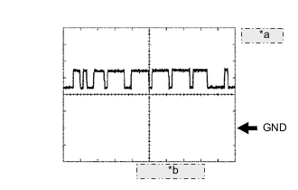
*a 1 V/DIV. *b 10 μsec./DIV. WAVEFORM 1
-
CAN communication signal
Item Content Terminal Name Between N173-8 (CA1P) and N173-28 (GND)
Between N173-10 (CA2H) and N173-28 (GND)
Tester Range 1 V/DIV., 10 μsec./DIV. Condition Power switch on (IG) Tech Tips
The waveform varies depending on the CAN communication signal.
-
-
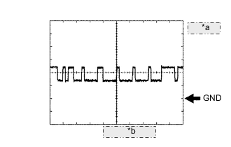
*a 1 V/DIV. *b 10 μsec./DIV. WAVEFORM 2
-
CAN communication signal
Item Content Terminal Name Between N173-9 (CA1N) and N173-28 (GND)
Between N173-11 (CA2L) and N173-28 (GND)
Tester Range 1 V/DIV., 10 μsec./DIV. Condition Power switch on (IG) Tech Tips
The waveform varies depending on the CAN communication signal.
-
-
-
CHECK MILLIMETER WAVE RADAR SENSOR

Terminal No. (Symbols) Wiring Color Terminal Description Condition Specified Condition B17-1 (SGND) - Body ground BR - Body ground Ground Always Below 1 Ω B17-2 (CA2L) - B17-1 (SGND) L - BR CAN communication signal Power switch on (IG) Pulse generation
(see waveform 2)
B17-3 (CA2H) - B17-1 (SGND) B - BR CAN communication signal Power switch on (IG) Pulse generation
(see waveform 1)
B17-5 (CA1P) - B17-1 (SGND) G - BR CAN communication signal Power switch on (IG) Pulse generation
(see waveform 1)
B17-6 (CA1N) - B17-1 (SGND) B - BR CAN communication signal Power switch on (IG) Pulse generation
(see waveform 2)
B17-8 (IGB) - B17-1 (SGND) W - BR Power source Power switch on (IG) 11 to 14 V
-
*a 1 V/DIV. *b 10 μsec./DIV. WAVEFORM 1
-
CAN communication signal
Item Content Terminal Name Between B17-3 (CA2H) and B17-1 (SGND)
Between B17-5 (CA1P) and B17-1 (SGND)
Tester Range 1 V/DIV., 10 μsec./DIV. Condition Power switch on (IG) Tech Tips
The waveform varies depending on the CAN communication signal.
-
-
*a 1 V/DIV. *b 10 μsec./DIV. WAVEFORM 2
-
CAN communication signal
Item Content Terminal Name Between B17-2 (CA2L) and B17-1 (SGND)
Between B17-6 (CA1N) and B17-1 (SGND)
Tester Range 1 V/DIV., 10 μsec./DIV. Condition Power switch on (IG) Tech Tips
The waveform varies depending on the CAN communication signal.
-
-