EXHAUST MANIFOLD INSTALLATION
PROCEDURE
-
INSTALL AIR FUEL RATIO SENSOR
-
INSTALL EXHAUST MANIFOLD SUB-ASSEMBLY LH
-
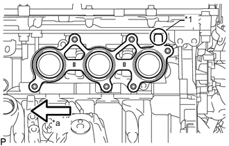
Text in Illustration *1 Protrusion *a Front Install a new gasket as shown in the illustration.
-
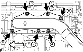
Text in Illustration *a Front Temporarily install the exhaust manifold sub-assembly LH with 6 new nuts.
-
Tighten the 6 nuts in the sequence shown in the illustration.
- Torque:
- 21 N*m { 214 kgf*cm, 15 ft.*lbf }
Note
-
When installing the exhaust manifold, make sure that the flange surface of the exhaust manifold is pressed against the engine and install the nuts in the order shown in the illustration. Make sure to tighten the nut that was tightened first twice at the end.
-
Make sure that the exhaust manifold is correctly fitted onto the stud bolts.
-
Connect the air fuel ratio sensor connector and attach the clamp.
-
-
INSTALL EXHAUST MANIFOLD SUB-ASSEMBLY RH
-
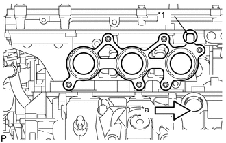
Text in Illustration *1 Protrusion *a Front Install a new gasket as shown in the illustration.
-
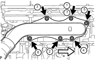
Text in Illustration *a Front Temporarily install the exhaust manifold sub-assembly RH with 6 new nuts.
-
Tighten the 6 nuts in the sequence shown in the illustration.
- Torque:
- 21 N*m { 214 kgf*cm, 15 ft.*lbf }
Note
-
When installing the exhaust manifold, make sure that the flange surface of the exhaust manifold is pressed against the engine and install the nuts in the order shown in the illustration. Make sure to tighten the nut that was tightened first twice at the end.
-
Make sure that the exhaust manifold is correctly fitted onto the stud bolts.
-
Connect the air fuel ratio sensor connector and attach the clamp.
-
-
INSTALL NO. 1 EXHAUST PIPE SUPPORT BRACKET SUB-ASSEMBLY
-
Install the No. 1 exhaust pipe support bracket sub-assembly with the 2 bolts.
- Torque:
- 43 N*m { 438 kgf*cm, 32 ft.*lbf }
-
-
INSTALL FRONT EXHAUST PIPE ASSEMBLY
-
CONNECT HEATED OXYGEN SENSOR (for Bank 2 Sensor 2)
-
Connect the heated oxygen sensor connector.
-
-
CONNECT HEATED OXYGEN SENSOR (for Bank 1 Sensor 2)
-
INSTALL FRONT CENTER FLOOR BRACE
-
INSTALL NO. 2 REAR FLOOR BOARD SUB-ASSEMBLY
-
INSTALL NO. 1 REAR FLOOR BOARD SUB-ASSEMBLY
-
INSTALL NO. 2 OIL LEVEL DIPSTICK GUIDE
-
Install a new O-ring to the No. 2 oil level dipstick guide.
-
Install the No. 2 oil level dipstick guide with the bolt.
- Torque:
- 21 N*m { 214 kgf*cm, 15 ft.*lbf }
-
Install the oil level dipstick.
-
-
INSTALL NO. 1 INVERTER COOLING PIPE (for LHD)
-
CONNECT AIR CONDITIONING HARNESS
-
INSTALL INVERTER RESERVOIR TANK ASSEMBLY (for LHD)
-
Install the inverter reservoir tank assembly with the 2 bolts.
- Torque:
- 13 N*m { 133 kgf*cm, 10 ft.*lbf }
-
Connect the No. 3 inverter cooling hose and No. 4 inverter cooling hose.
-
-
CONNECT NO. 3 ENGINE ROOM RELAY BLOCK
-
INSTALL SKID CONTROL ECU ASSEMBLY
-
INSTALL NO. 5 INVERTER BRACKET
-
Install the No. 5 inverter bracket with the 3 bolts.
- Torque:
- 8.0 N*m { 82 kgf*cm, 71 in.*lbf }
-
for LHD:
Connect the No. 4 floor wire with the nut.
- Torque:
- 8.0 N*m { 82 kgf*cm, 71 in.*lbf }
-
-
INSTALL WIRE HARNESS CLAMP BRACKET A (for RHD)
-
Install the wire harness clamp bracket A with the 2 nuts.
- Torque:
- 5.5 N*m { 56 kgf*cm, 49 in.*lbf }
-
-
INSTALL ECM
-
INSTALL AIR CLEANER CASE SUB-ASSEMBLY
-
INSTALL AIR CLEANER FILTER ELEMENT SUB-ASSEMBLY
-
INSTALL AIR CLEANER CAP WITH AIR CLEANER HOSE
-
INSTALL POWER STEERING ECU ASSEMBLY
-
INSTALL INVERTER WITH CONVERTER ASSEMBLY
-
INSPECT FOR EXHAUST GAS LEAK