EXHAUST MANIFOLD REMOVAL
PROCEDURE
-
REMOVE INVERTER WITH CONVERTER ASSEMBLY
-
REMOVE POWER STEERING ECU ASSEMBLY
-
REMOVE AIR CLEANER CAP WITH AIR CLEANER HOSE
-
REMOVE AIR CLEANER FILTER ELEMENT SUB-ASSEMBLY
-
REMOVE AIR CLEANER CASE SUB-ASSEMBLY
-
REMOVE ECM
-
REMOVE WIRE HARNESS CLAMP BRACKET A (for RHD)
-
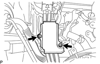
Remove the 2 nuts and wire harness clamp bracket A.
-
-
REMOVE NO. 5 INVERTER BRACKET
-
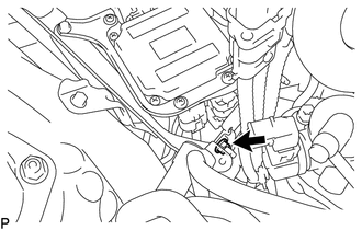
for LHD:
Remove the nut and disconnect the No. 4 floor wire.
-
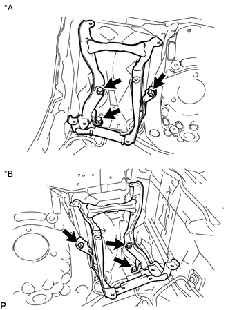
Text in Illustration *A for RHD *B for LHD Remove the 3 bolts and No. 5 inverter bracket.
-
-
REMOVE SKID CONTROL ECU ASSEMBLY
-
DISCONNECT NO. 3 ENGINE ROOM RELAY BLOCK
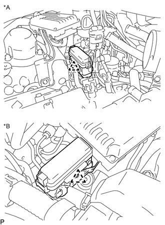
Text in Illustration *A for RHD *B for LHD -
REMOVE INVERTER RESERVOIR TANK ASSEMBLY (for LHD)
-
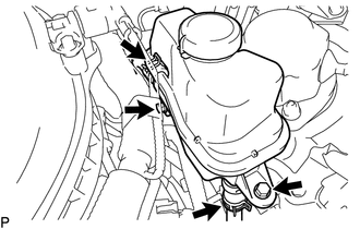
Disconnect the No. 3 inverter cooling hose and No. 4 inverter cooling hose.
-
Remove the 2 bolts and inverter reservoir tank assembly.
-
-
DISCONNECT AIR CONDITIONING HARNESS
-
REMOVE NO. 1 INVERTER COOLING PIPE (for LHD)
-
REMOVE NO. 2 OIL LEVEL DIPSTICK GUIDE
-
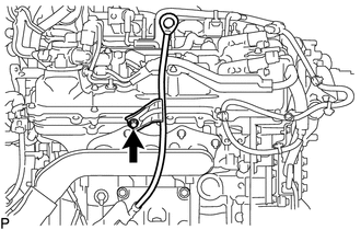
Remove the oil level dipstick.
-
Remove the bolt and No. 2 oil level dipstick guide.
-
Remove the O-ring from the No. 2 oil level dipstick guide.
-
-
REMOVE NO. 1 REAR FLOOR BOARD SUB-ASSEMBLY
-
REMOVE NO. 2 REAR FLOOR BOARD SUB-ASSEMBLY
-
REMOVE FRONT CENTER FLOOR BRACE
-
DISCONNECT HEATED OXYGEN SENSOR (for Bank 1 Sensor 2)
-
DISCONNECT HEATED OXYGEN SENSOR (for Bank 2 Sensor 2)
-
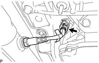
Disconnect the heated oxygen sensor connector.
-
-
REMOVE FRONT EXHAUST PIPE ASSEMBLY
-
REMOVE NO. 1 EXHAUST PIPE SUPPORT BRACKET SUB-ASSEMBLY
-
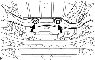
Remove the 2 bolts and No. 1 exhaust pipe support bracket sub-assembly.
-
-
REMOVE EXHAUST MANIFOLD SUB-ASSEMBLY RH
-
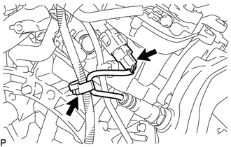
Detach the clamp and disconnect the air fuel ratio sensor connector.
-
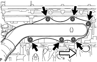
Text in Illustration *a Front Remove the 6 nuts, exhaust manifold sub-assembly RH and gasket.
-
-
REMOVE EXHAUST MANIFOLD SUB-ASSEMBLY LH
-
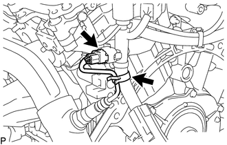
Detach the clamp and disconnect the air fuel ratio sensor connector.
-
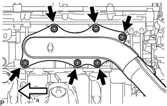
Text in Illustration *a Front Remove the 6 nuts, exhaust manifold sub-assembly LH and gasket.
-
-
REMOVE AIR FUEL RATIO SENSOR