INTAKE MANIFOLD INSTALLATION
PROCEDURE
-
INSTALL STUD BOLT
Note
If a stud bolt is deformed or its threads are damaged, replace it.
-
Using an E6 "TORX" socket wrench, install the 4 stud bolts to the intake manifold.
- Torque:
- 4.0 N*m { 41 kgf*cm, 35 in.*lbf }
-
-
INSTALL EGR HOLE COVER PLATE (w/o EGR System)
-
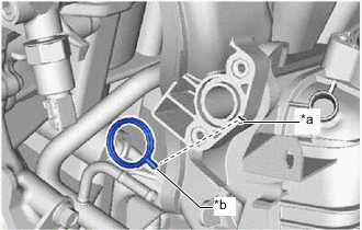
Text in Illustration *a Groove *b Protrusion Install a new EGR inlet gasket and EGR hole cover plate to the intake manifold with the 2 nuts.
- Torque:
- 10 N*m { 102 kgf*cm, 7 ft.*lbf }
Note
Align the protrusion of the EGR inlet gasket with the groove of the intake manifold.
-
-
INSTALL INTAKE MANIFOLD
-
Install a new gasket to the intake manifold.
-
Temporarily install the intake manifold and intake manifold stay with the 7 bolts.
Tech Tips
If an intake manifold stay is deformed or damaged, replace it.
-
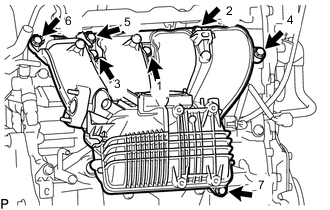
Tighten the 7 bolts in the order shown in the illustration.
- Torque:
- 28 N*m { 286 kgf*cm, 21 ft.*lbf }
-
Install the 2 wire harness clamp brackets to the intake manifold with the 3 bolts.
- Torque:
- 10 N*m { 102 kgf*cm, 7 ft.*lbf }
-
Attach the clamp to connect the No. 2 water by-pass hose to the intake manifold.
-
Attach the 7 wire harness clamps to connect the wire harness to the 2 wire harness clamp brackets and intake manifold.
-
Attach the clamp to connect the ventilation hose to the wire harness clamp bracket.
-
Connect the ventilation hose to the intake manifold, and slide the clip to secure the hose.
-
Connect the No. 2 fuel vapor feed hose to the intake manifold.
-
Attach the clamp to connect the fuel tube to the wire harness clamp bracket.
-
-
INSTALL NO. 2 EGR PIPE (w/ EGR System)
-
INSTALL OUTLET HEATER WATER HOSE A
-
Install the water hose set to the outlet heater water hose A.
-
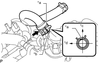
Text in Illustration *a Paint Mark *b Protrusion *c Upper Side of Vehicle *d Front Side of Vehicle Install the outlet heater water hose A to the No. 2 water by-pass pipe, and slide the hose clamp to secure the hose.
Tech Tips
The direction of the hose clamp is indicated in the illustration.
-
Connect the outlet heater water hose A to the heater unit, and slide the hose clamp to secure the hose.
-
-
CONNECT INLET HEATER WATER HOSE A
-
INSTALL PURGE VSV
-
INSTALL VACUUM SENSOR ASSEMBLY
-
CONNECT INVERTER RESERVE TANK ASSEMBLY (for RHD)
-
Install the inverter reserve tank assembly to the No. 1 inverter reserve tank bracket with the 2 bolts.
- Torque:
- 13 N*m { 127 kgf*cm, 9 ft.*lbf }
-
-
INSTALL INJECTOR DRIVER
-
INSTALL THROTTLE BODY WITH MOTOR ASSEMBLY
-
INSTALL NO. 1 AIR CLEANER INLET
-
INSTALL COOL AIR INTAKE DUCT SEAL
-
INSTALL ENGINE ROOM SIDE COVER