PURGE VALVE INSPECTION
PROCEDURE
-
INSPECT PURGE VSV
-
Measure the resistance according to the value(s) in the table below.
Standard Resistance Tester Connection Condition Specified Condition 1 - 2 20°C (68°F) 23 to 26 Ω 1 - Body ground Always 10 MΩ or higher 2 - Body ground If the result is not as specified, replace the purge VSV.
-
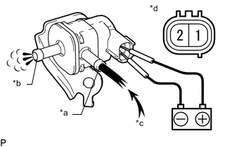
Text in Illustration *a Port E *b Port F *c Air *d Component without wire harness connected
(Purge VSV)
Apply auxiliary battery voltage between the terminals of the purge VSV and check that the following occurs when blowing air into port E.
OK Measurement Condition Specified Condition Auxiliary battery positive (+) - Terminal 1
Auxiliary battery negative (-) Terminal 2
Air flows from port F Auxiliary battery voltage not applied between terminals 1 and 2 Air does not flow If the result is not as specified, replace the purge VSV.
-