FUEL PRESSURE SENSOR INSTALLATION

PROCEDURE
-
INSTALL FUEL PRESSURE SENSOR
-
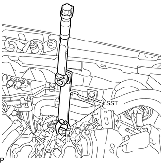
Using SST, install the fuel pressure sensor to the fuel delivery pipe.
- SST
- 09922-10240
- 09961-01270
- Torque:
- without SST
- 40 N*m { 408 kgf*cm, 30 ft.*lbf }
- with SST
- 17 N*m { 175 kgf*cm, 13 ft.*lbf }
Note
-
Be sure not to damage or allow any foreign matter on the threads and tip of the fuel pressure sensor.
-
Do not get any oil on the threads of the fuel pressure sensor and fuel delivery pipe.
-
Do not allow the fuel pressure sensor to be contaminated with foreign matter when assembling.
-
Do not adjust the torque in the loosening direction.
Tech Tips
-
This torque value is effective when SST is parallel to the torque wrench.
-
This torque value can be obtained by using a torque wrench with a fulcrum length of 300 mm (11.8 in.) and SST with a fulcrum length of 240 mm (9.45 in.).
-
If using a torque wrench with a length that is not 300 mm (11.8 in.), calculate the torque specification for the torque wrench and SST based on the "without SST" torque specification Click here.
-
Connect the connector.
Note
Do not pull the wire harness of the fuel pressure sensor excessively.
-
-
INSTALL NO. 2 FUEL PIPE SUB-ASSEMBLY
-
INSTALL NO. 3 WATER BY-PASS PIPE
-
Connect the 2 water by-pass hoses and install the No. 3 water by-pass pipe.
-
Install the bolt.
- Torque:
- 10 N*m { 102 kgf*cm, 7 ft.*lbf }
-
Attach the 2 wire harness clamps to the No. 3 water by-pass pipe.
-
Connect the 2 heater water hoses.
-
Install the 2 water hose sets.
-
-
INSTALL INTAKE MANIFOLD