FUEL PRESSURE SENSOR INSPECTION

PROCEDURE
-
INSPECT FUEL PRESSURE SENSOR
-
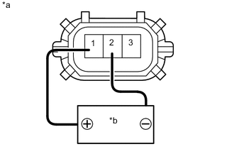
Text in Illustration *a Component without harness connected
(Fuel Pressure Sensor)
*b Voltage applied between terminals Check the fuel pressure sensor output voltage.
-
Apply 5 V between terminals 1 (VC) and 2 (E2).
Note
-
Be careful when connecting the leads, as the fuel pressure sensor may be damaged if the leads are connected to the wrong terminals.
-
Do not apply a voltage of 6V or higher to terminals 1 (VC) and 2 (E2).
Tech Tips
If a stable power supply is not available, use 4 1.2 V nickel-metal hydride batteries, etc.
-
-
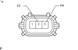
Text in Illustration *a Component without harness connected
(Fuel Pressure Sensor)
Measure the voltage between terminals.
Standard Voltage Tester Connection Condition Specified Condition 3 (PR) - 2 (E2) Pressure not applied to fuel pressure sensor Approximately 0.42 to 0.58 V* *: The output voltage changes depending on the voltage applied to the terminals.
Output voltage = (0.08 x Voltage applied to terminals) to (0.12 x Voltage applied to terminals)
If the result is not as specified, replace the fuel pressure sensor.
-
-