FUEL INJECTOR(for Direct Injection) INSTALLATION

CAUTION / NOTICE / HINT
Tech Tips
Perform "Inspection After Repairs" after replacing the fuel injector Click here.
PROCEDURE
-
INSTALL FUEL INJECTOR SEAL
-
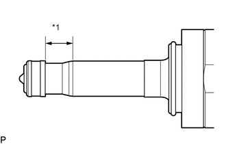
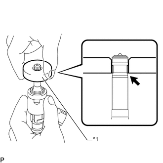
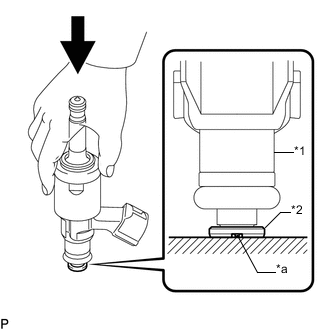
Text in Illustration *1 Clean Area Apply engine conditioner to the injector area shown in the illustration. Using a piece of cloth, clean carbon deposits from the injector and its grooves.
Note
-
Do not clean the tip of the injector.
-
Do not use a wire brush to clean the injector.
-
If an injector is dropped or the tips of the injectors are struck, replace it with a new one.
-
-
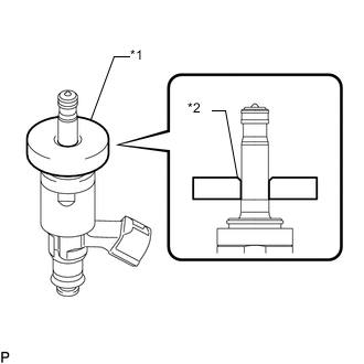
Text in Illustration *1 SST (Guide) *2 Tapered Inner Portion Apply engine oil to the injector contact surface of SST (guide). Then attach SST (guide) to the injector with the tapered inner portion facing the tip of the injector as shown in the illustration.
- SST
- 09260-39021 ( 09261-03020 )
-
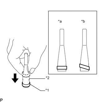
Text in Illustration *1 Fuel Injector Seal *2 SST (Holder) *a CORRECT *b INCORRECT Install a new injector seal to SST (holder).
- SST
- 09260-39021 ( 09261-03011 )
Note
Be careful not to install the injector seal to SST (holder) at an angle. Doing so will stretch the seal and correcting this problem is very complicated.
-
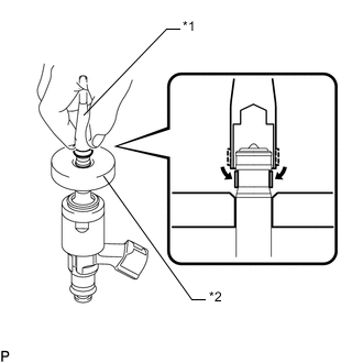
Text in Illustration *1 SST (Holder) *2 SST (Guide) Install SST (holder with injector seal) to the tip of the injector. Slide the seal downward into the injector groove (injector connector side) with your fingers as shown in the illustration.
- SST
- 09260-39021 ( 09261-03011, 09261-03020 )
Tech Tips
Check that the seal covers the circumference of the injector groove as shown in the illustration.
-
Text in Illustration *1 SST (Guide) Slowly slide SST (guide) toward the tip of the injector. When the injector contact surface of SST (guide) aligns with the seal (injector tip side) as shown in the illustration, hold the position for 5 seconds or more to fully align the seal into the injector groove.
- SST
- 09260-39021 ( 09261-03020 )
Note
Be careful that the seal is not pinched between SST (guide) and the injector groove. Replace the seal if it becomes damaged.
Tech Tips
-
Set SST (guide) so that its bottom surface and the seal are flush.
-
If there is difficulty in sliding SST upward, slowly wiggle it from side to side while sliding it up the injector little by little.
-
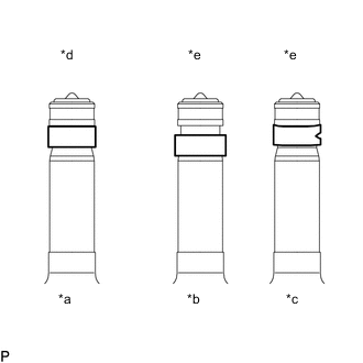
Text in Illustration *a Normal *b Protruding *c Deformed *d CORRECT *e INCORRECT After installing the seals, check that they are not scratched, deformed or protruding from the injector groove.
Note
If a seal is scratched, deformed or protruding from the groove, replace it with a new one.
-
-
INSTALL FUEL INJECTOR ASSEMBLY
Tech Tips
Perform "Inspection After Repairs" after replacing the fuel injector Click here.
-
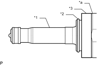
Text in Illustration *1 Injector Assembly *2 C-ring *3 Injector Vibration Insulator *a Tapered Side Install a new injector vibration insulator and a new C-ring to the injector assembly.
Note
-
Install the injector vibration insulator aligning it with the tapered side of the injector assembly.
-
Check that the C-ring is securely fit into the groove of the injector assembly.
-
-
Install a new No. 1 fuel injector back-up ring and a new O-ring as shown in the illustration.
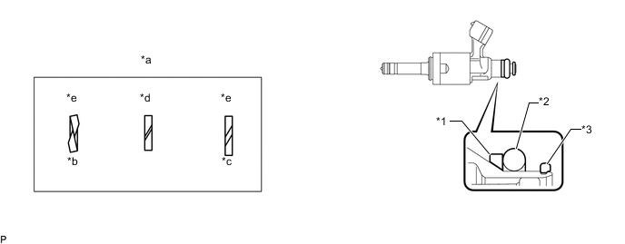
Text in Illustration *1 No. 1 Fuel Injector Back-up Ring *2 O-ring *3 No. 3 Fuel Injector Back-up Ring - - *a No. 1 Fuel Injector Back-up Ring Opening *b Overlapping *c Gap *d OK *e NG - - Note
-
Check that there is no foreign matter or damage in the groove of the O-ring.
-
Do not mistake the direction of the No. 1 fuel injector back-up ring.
-
Do not install the No. 1 fuel injector back-up ring and O-ring in the wrong order.
-
Do not allow the opening of the No. 1 fuel injector back-up ring to separate or overlap as shown in the illustration.
-
-
Text in Illustration *1 Fuel injector assembly *2 No. 3 Fuel Injector Back-up Ring *a Cutout Set a new No. 3 fuel injector back-up ring so that it is level as shown in the illustration, push in the injector assembly and install the No. 3 fuel injector back-up ring.
Note
-
Make sure that the No. 3 fuel injector back-up ring is oriented correctly.
-
After installing the O-ring, make sure there is no damage or foreign matter.
-
-
Install the nozzle holder clamp to the injector.
-
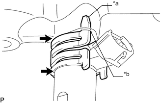
Text in Illustration *a Protrusion *b Positioning Hole 
No gap 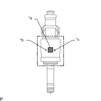
Text in Illustration *a QR Code *b Flow Classification Number *c Oil Seal Classification Number Align the protrusion of the nozzle holder clamp with the positioning hole of the fuel delivery pipe and insert the injector.
Note
-
Install 3 injectors with the same flow classification number (the number to the left of the QR code which is 1, 2 or 3) on each bank (6 injectors with the same flow classification number is also okay).
-
Install an injector with an oil seal classification number (the number to the right of the QR code) of either 4 or 5.
-
Make sure that there is no foreign matter or damage inside the injector insertion holes (fuel delivery pipe).
-
Do not get gasoline on the O-rings or inside the installation holes.
-
If the injector is difficult to insert, apply new engine oil to the chamfered part of the injector insertion hole of the fuel delivery pipe. Also, be careful as it is easier for the injector to fall out of the fuel delivery pipe in this case.
-
Keep the injector straight and do not tilt it when inserting it into the fuel delivery pipe.
-
Check that there is no gap between the fuel delivery pipe and the nozzle holder clamp.
-
-
-
INSTALL FUEL DELIVERY PIPE RH
-
Apply lubricant to the installation hole of the injector.
-
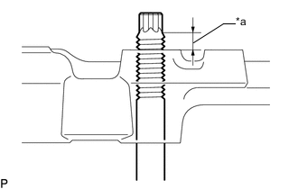
Text in Illustration *a Nut can be attached Insert the stud bolt into the fuel delivery pipe until the screw threads protrude enough so that a nut can be attached.
Note
-
If an injector is dropped or the tips of the injectors are struck, replace it with a new one.
-
Check that there is no foreign matter or damage to the injector insertion hole of the delivery pipe.
-
When inserting the fuel delivery pipe, push it in evenly without tilting it.
-
-
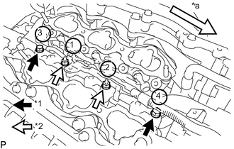
Text in Illustration *1 Bolt *2 Nut *a Front Install the fuel delivery pipe RH by uniformly tightening the 2 bolts and 2 nuts in several passes in the order shown in the illustration.
- Torque:
- Type A
- 32 N*m { 326 kgf*cm, 24 ft.*lbf }
- Type B
- 26 N*m { 265 kgf*cm, 19 ft.*lbf }
-
Install the bolt and attach the wire harness clamp.
- Torque:
- 10 N*m { 102 kgf*cm, 7 ft.*lbf }
-
Connect the fuel pressure sensor connector.
Note
Do not pull the wire harness of the fuel pressure sensor excessively.
-
-
INSTALL FUEL DELIVERY PIPE LH
-
Apply lubricant to the installation holes of the injectors.
-
Text in Illustration *a Nut can be attached Insert the stud bolt into the delivery pipe until the screw threads protrude enough so that a nut can be attached.
Note
-
If an injector is dropped or the tips of the injectors are struck, replace it with a new one.
-
Check that there is no foreign matter or damage to the injector insertion hole of the delivery pipe.
-
When inserting the fuel delivery pipe, push it in evenly without tilting it.
-
-
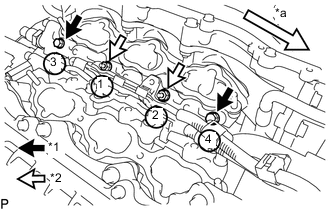
Text in Illustration *1 Bolt *2 Nut *a Front Install the fuel delivery pipe LH by uniformly tightening the 2 bolts and 2 nuts in several passes in the order shown in the illustration.
- Torque:
- Type A
- 32 N*m { 326 kgf*cm, 24 ft.*lbf }
- Type B
- 26 N*m { 265 kgf*cm, 19 ft.*lbf }
-
Install the bolt and attach the 2 wire harness clamps.
- Torque:
- 10 N*m { 102 kgf*cm, 7 ft.*lbf }
-
-
INSTALL NO. 2 FUEL PIPE SUB-ASSEMBLY
-
Temporarily install the 2 union nuts of the fuel delivery pipe to the No. 2 fuel pipe sub-assembly until they are completely fastened.
-
Use a 17 mm union nut wrench, tighten the 2 union nuts of the No. 2 fuel pipe sub-assembly.
- Torque:
- 35 N*m { 357 kgf*cm, 26 ft.*lbf }
Note
-
If the 2 union nuts cannot be fastened, loosen the nuts of the fuel delivery pipe RH and fuel delivery pipe LH, and then fasten both union nuts.
-
When a torque wrench is combined with a union nut wrench and used to tighten parts, if the reading from the torque wrench reaches the torque specification, the actual torque will be excessive due to the increase in the total length of the wrench Click here.
-
Do not adjust the torque in the loosening direction.
-
The No. 2 fuel pipe sub-assembly can be reused 10 times.
Tech Tips
-
This torque value is effective when the union nut wrench is parallel to the torque wrench.
-
Install the union nut wrench parallel with the torque wrench.
-
-
INSTALL FUEL PUMP ASSEMBLY (for High Pressure)