FUEL SENDER GAUGE ASSEMBLY REMOVAL

PROCEDURE
-
REMOVE FUEL SUCTION TUBE ASSEMBLY WITH PUMP AND GAUGE
-
REMOVE FUEL SENDER GAUGE ASSEMBLY
-
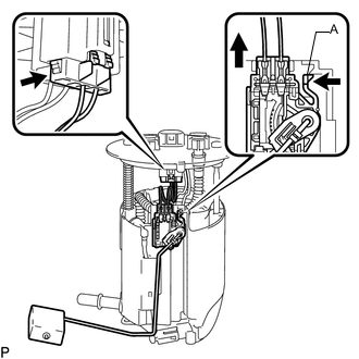
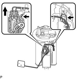
Disconnect the fuel sender gauge connector.
-
Push the claw labeled A of the fuel sender gauge assembly, and then pull up the fuel sender gauge assembly to remove it.
Note
-
Do not touch the resistance plate or contacts of the fuel sender gauge assembly.
-
Do not bend the arm of the fuel sender gauge assembly.
-
-
-
REMOVE REAR FLOOR SERVICE HOLE COVER
-
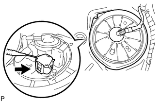
Remove the rear floor service hole cover.
-
Disconnect the fuel sender gauge connector.
-
-
REMOVE FUEL TANK VENT TUBE ASSEMBLY
-
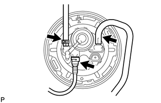
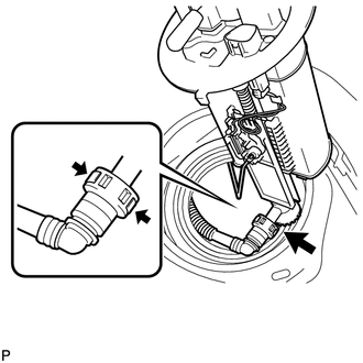
Slide the clip and disconnect the fuel tank evap/vent tube from the fuel tank vent tube sub-assembly.
-
Disconnect the charcoal canister outlet hose from the fuel tank vent tube sub-assembly.
-
Slide the clamp and disconnect the No. 1 fuel evaporation tube from the fuel tank vent tube sub-assembly.
-
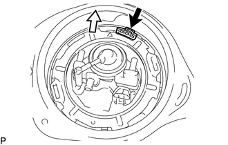
Release the lock and remove the No. 1 fuel tube clamp.
Text in Illustration 
Front of Vehicle -
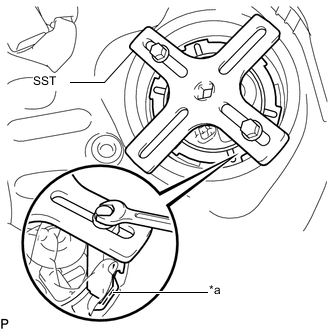
Text in Illustration *a Insertion Point Set the 2 claws and plate of SST on the fuel pump gauge retainer.
- SST
- 09808-14030 ( 09808-01010, 09808-01030, 09808-01040 )
Tech Tips
Securely insert the ends of SST into the insertion points in the fuel pump gauge retainer.
-
While firmly pressing the claws of SST into the insertion points in the fuel pump gauge retainer, tighten the bolts of the claws.
-
Attach the handle of SST.
-
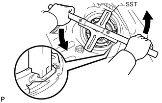
Using SST, loosen the fuel pump gauge retainer.
Note
-
Do not use any tools other than SST, such as a screwdriver, etc.
-
Do not use excessive force when pressing down on SST, as the fuel pump gauge retainer will place excessive force on the fuel tank vent tube assembly and be difficult to remove, and parts may be damaged.
-
Be sure to keep the handle level when turning it, as SST may slip off the retainer if the handle is turned at an angle with excessive force.
-
Do not use an impact wrench or turn the handle with excessive force, as parts may be damaged.
-
If SST slips off the retainer, loosen the bolts and reattach SST to the retainer.
-
Make sure that the fuel suction tube set gasket does not come off.
-
-
While pressing down on the fuel tank vent tube assembly with your hand, remove the fuel pump gauge retainer.
-
Disconnect the fuel return vent tube sub-assembly and remove the fuel tank vent tube assembly from the fuel tank assembly.
Note
When disconnecting the fuel tube connector, do not excessively pull on the fuel return vent tube sub-assembly.
-
Remove the fuel suction tube set gasket from the fuel tank assembly.
-
-
REMOVE NO. 2 FUEL SENDER GAUGE ASSEMBLY
-
Disconnect the fuel sender gauge connector.
-
Push the claw labeled A of the No. 2 fuel sender gauge assembly, and then pull up the No. 2 fuel sender gauge assembly to remove it.
Note
-
Do not touch the resistance plate or contacts of the No. 2 fuel sender gauge assembly.
-
Do not bend the arm of the No. 2 fuel sender gauge assembly.
-
-