FUEL PUMP REMOVAL

PROCEDURE
-
DISCHARGE FUEL SYSTEM PRESSURE
-
PRECAUTION
Note
After turning the power switch off, waiting time may be required before disconnecting the cable from the auxiliary battery terminal. Therefore, make sure to read the disconnecting the cable from the auxiliary battery terminal notice before proceeding with work Click here.
-
DISCONNECT CABLE FROM NEGATIVE AUXILIARY BATTERY TERMINAL
Note
When disconnecting the cable, some systems need to be initialized after the cable is reconnected Click here.
-
REMOVE BENCH TYPE REAR SEAT CUSHION ASSEMBLY
-
REMOVE NO. 3 ROOM PARTITION PAD
-
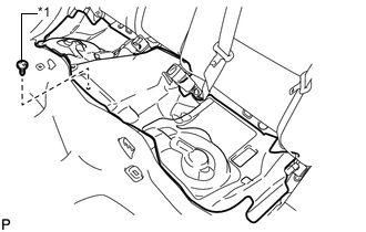
Text in Illustration *1 Clip Remove the clip and No. 3 room partition pad.
-
-
REMOVE REAR FLOOR SERVICE HOLE COVER
-
Remove the rear floor service hole cover.
-
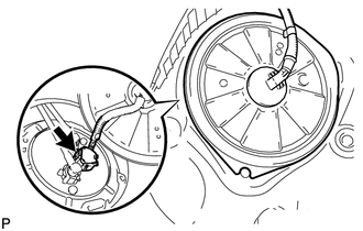
Disconnect the fuel pump connector.
-
-
REMOVE FUEL SUCTION TUBE ASSEMBLY WITH PUMP AND GAUGE
-
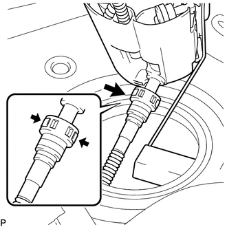
Disconnect the fuel tank main tube sub-assembly and fuel tank return tube.
-
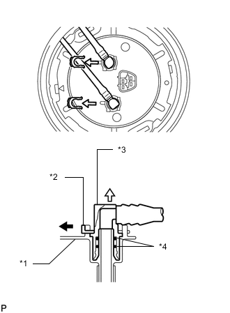
Text in Illustration *1 Fuel Suction Plate Sub-assembly *2 Tube Joint Clip *3 Fuel Tube Joint *4 O-Ring Remove the 2 tube joint clips, fuel tank main tube sub-assembly and fuel tank return tube.
Note
-
Remove any dirt and foreign matter on the fuel tube joint before performing this step.
-
Do not allow any scratches or foreign matter on the parts when disconnecting them as the fuel tube joint contains the O-rings that seal the plug.
-
Perform this step by hand. Do not use any tools.
-
Do not forcibly bend, twist or turn the nylon tube.
-
Protect the disconnected part by covering it with a plastic bag and tape after disconnecting the fuel tube.
-
-
-
Release the lock and remove the No. 1 fuel tube clamp.
Text in Illustration 
Front of Vehicle -
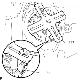
Remove the fuel pump gauge retainer.
-
Set the 2 claws and plate of SST on the fuel pump gauge retainer.
- SST
- 09808-14030 ( 09808-01010, 09808-01030, 09808-01040 )
Text in Illustration *1 Insertion Point Tech Tips
Securely insert the ends of SST into the insertion points in the fuel pump gauge retainer.
-
While firmly pressing the claws of SST into the insertion points in the fuel pump gauge retainer, tighten the bolts of the claws.
-
Attach the handle of SST.
-
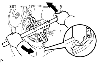
While lightly pressing down on SST so it does not come off the retainer, slowly turn the handle and remove the fuel pump gauge retainer.
Note
-
Do not use any tools other than SST, such as a screwdriver, etc.
-
Do not use excessive force when pressing down on SST, as the fuel pump gauge retainer will place excessive force on the fuel suction tube assembly with pump and gauge and be difficult to remove, and parts may be damaged.
-
Be sure to keep the handle level when turning it, as SST may slip off the retainer if the handle is turned at an angle with excessive force.
-
Do not use an impact wrench or turn the handle with excessive force, as parts may be damaged.
-
If SST slips off the retainer, loosen the bolts and reattach SST to the retainer.
-
-
-
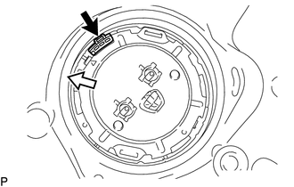
Disconnect the fuel return vent tube sub-assembly.
-
Remove the fuel suction tube assembly with pump and gauge from the fuel tank assembly.
Note
-
Make sure that the fuel sender gauge arm does not bend.
-
Do not damage the fuel return vent tube sub-assembly.
-
-
Remove the fuel suction tube set gasket from the fuel tank assembly.
-