ENGINE UNIT INSTALLATION

PROCEDURE
-
INSTALL ENGINE COVER
-
INSTALL ENGINE COOLANT TEMPERATURE SENSOR
-
INSTALL ENGINE OIL PRESSURE SWITCH ASSEMBLY
-
INSTALL ENGINE OIL LEVEL SENSOR
-
INSTALL IGNITION COIL ASSEMBLY
-
INSTALL V-BANK COVER BOLT
-
Install the V-bank cover bolt.
- Torque:
- 10 N*m { 102 kgf*cm, 7 ft.*lbf }
-
-
INSTALL V-BANK COVER BRACKET SUB-ASSEMBLY
-
Install the V-bank cover bracket with the bolt.
- Torque:
- 10 N*m { 102 kgf*cm, 7 ft.*lbf }
-
-
INSTALL FUEL INJECTOR SEAL
-
INSTALL FUEL INJECTOR ASSEMBLY
-
INSTALL FUEL DELIVERY PIPE RH
-
INSTALL FUEL DELIVERY PIPE LH
-
INSTALL NO. 2 FUEL PIPE SUB-ASSEMBLY
-
SET FUEL PUMP ASSEMBLY
-
TEMPORARILY INSTALL NO. 1 FUEL PIPE SUB-ASSEMBLY
-
INSTALL FUEL PUMP ASSEMBLY
-
INSTALL NO. 1 FUEL PIPE SUB-ASSEMBLY
-
INSTALL NO. 3 WATER BY-PASS PIPE
-
Connect the 2 hoses, and install the bolt and No. 3 water by-pass pipe.
- Torque:
- 10 N*m { 102 kgf*cm, 7 ft.*lbf }
-
-
INSTALL INTAKE MANIFOLD
-
INSTALL NO. 2 SURGE TANK STAY
-
Install the No. 2 surge tank stay with the bolt.
- Torque:
- 21 N*m { 214 kgf*cm, 15 ft.*lbf }
-
-
INSTALL INTAKE AIR SURGE TANK ASSEMBLY
-
INSTALL THROTTLE BODY WITH MOTOR ASSEMBLY
-
INSTALL INJECTOR DRIVER
-
INSTALL ENGINE WIRE
-
INSTALL WATER PUMP PULLEY
-
INSTALL V-RIBBED BELT TENSIONER ASSEMBLY
-
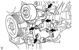
Temporarily install the V-ribbed belt tensioner with the 5 bolts.
Standard Bolt Item Length A 70 mm (2.76 in.) B 35 mm (1.38 in.) -
Install the V-ribbed belt tensioner by tightening the bolt 1 and bolt 2 in the order shown in the illustration.
- Torque:
- 43 N*m { 438 kgf*cm, 32 ft.*lbf }
-
Tighten the other bolts.
- Torque:
- 43 N*m { 438 kgf*cm, 32 ft.*lbf }
-
-
INSTALL FRONT NO. 1 ENGINE MOUNTING BRACKET LH
-
Install the front No. 1 engine mounting bracket LH with the 4 bolts.
- Torque:
- 43 N*m { 438 kgf*cm, 32 ft.*lbf }
-
Connect the 2 clamps.
-
-
INSTALL FRONT NO. 1 ENGINE MOUNTING BRACKET RH
-
Install the front No. 1 engine mounting bracket RH with the 4 bolts.
- Torque:
- 43 N*m { 438 kgf*cm, 32 ft.*lbf }
-
-
INSTALL NO. 1 ENGINE COVER
-
INSTALL NO. 2 ENGINE COVER
-
Install the No. 2 engine cover with the 3 clips.
-
Connect the clamp.
-