ENGINE ASSEMBLY REMOVAL
CAUTION / NOTICE / HINT
CAUTION:
As the engine assembly with transmission is extremely heavy, the engine lifter may suddenly drop if the instructions listed in the repair manual are not followed. Therefore, always follow the instructions listed in the repair manual when performing this procedure.
PROCEDURE
-
REMOVE ENGINE ROOM SIDE COVER
-
Remove the 4 clips and engine room side cover.
-
-
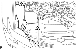
REMOVE COOL AIR INTAKE DUCT SEAL
-
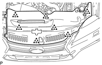
Remove the 7 clips and cool air intake duct seal.
-
-
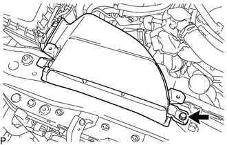
REMOVE V-BANK COVER SUB-ASSEMBLY
-
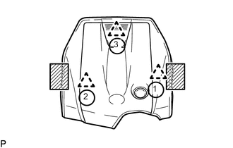
Place both hands on the sides of the cover as shown in the illustration, lift the cover to detach the 2 clips near the front in the order shown in the illustration, and then lift the cover further to detach the rear clip and remove the cover.
Text in Illustration 
Areas to place hands when lifting cover Note
If the cover is lifted rearward or forward and to the right or left at the same time, the cover may be damaged.
-
-
RECOVER REFRIGERANT FROM AIR CONDITIONING SYSTEM (for HFC-134a(R134a))
-
DISCHARGE FUEL SYSTEM PRESSURE
-
PLACE FRONT WHEELS FACING STRAIGHT AHEAD
-
REMOVE LUGGAGE COMPARTMENT FLOOR MAT
-
REMOVE LUGGAGE COMPARTMENT TRIM COVER LH
-
PRECAUTION
CAUTION:
Be sure to read Precaution thoroughly before servicing Click here.
Note
After turning the power switch off, waiting time may be required before disconnecting the cable from the auxiliary battery terminal. Therefore, make sure to read the disconnecting the cable from the auxiliary battery terminal notice before proceeding with work Click here.
-
DISCONNECT CABLE FROM NEGATIVE AUXILIARY BATTERY TERMINAL
Note
When disconnecting the cable, some systems need to be initialized after the cable is reconnected Click here.
-
REMOVE NO. 1 SEAT ARMREST CAP
-
REMOVE LOWER HYBRID VEHICLE BATTERY COVER PANEL
-
REMOVE SERVICE PLUG GRIP
-
REMOVE INVERTER COVER
-
REMOVE CONNECTOR COVER ASSEMBLY
-
CHECK TERMINAL VOLTAGE
-
TEMPORARILY INSTALL CONNECTOR COVER ASSEMBLY
-
REMOVE INVERTER MOTOR CABLE BRACKET ASSEMBLY
-
REMOVE INVERTER TERMINAL COVER
-
REMOVE FRONT WHEEL
-
REMOVE ENGINE UNDER COVER
-
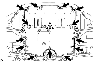
Remove the 13 screws, 3 clips and engine under cover.
-
-
REMOVE REAR ENGINE UNDER COVER LH
-
Remove the screw and rear engine under cover LH.
-
-
REMOVE REAR ENGINE UNDER COVER RH
Tech Tips
Remove the RH side following the same procedure as for the LH side.
-
REMOVE FRONT SUSPENSION MEMBER BRACE
-
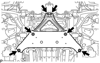
w/ Canister Pump Module:
Remove the 6 bolts and front suspension member brace.
-
w/o Canister Pump Module:
Remove the 4 bolts, and then turn the clip and remove the front suspension member brace.
Tech Tips
Do not remove the clip from the front suspension member brace.
-
-
REMOVE NO. 2 ENGINE UNDER COVER
-
Remove the 4 screws, 2 grommets and No. 2 engine under cover.
-
-
DRAIN ENGINE OIL
-
DRAIN ENGINE COOLANT
-
DRAIN COOLANT (for Inverter)
-
REMOVE NO. 1 AIR CLEANER INLET
-
Remove the bolt and No. 1 air cleaner inlet.
-
-
REMOVE AIR CLEANER CAP WITH AIR CLEANER HOSE
-
REMOVE AIR CLEANER FILTER ELEMENT SUB-ASSEMBLY
-
REMOVE AIR CLEANER CASE SUB-ASSEMBLY
-
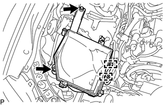
Remove the 2 bolts, 2 clamps and air cleaner case sub-assembly.
Note
When removing the air cleaner case sub-assembly, be careful not to lose the grommet on the underside of the air cleaner case.
-
-
DISCONNECT WIRE HARNESS
-
REMOVE OIL PUMP MOTOR CONTROLLER
-
REMOVE WIRING HARNESS PROTECTOR
-
REMOVE HEATER ACCESSORY ASSEMBLY
-
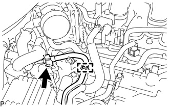
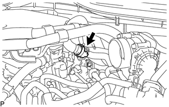
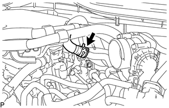
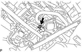
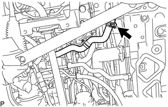
DISCONNECT PURGE LINE HOSE
-
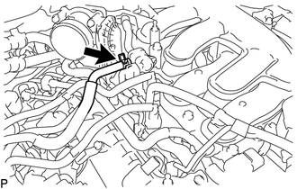
Remove the clamp and disconnect the purge line hose.
-
-
DISCONNECT NO. 3 FUEL TUBE SUB-ASSEMBLY
-
Disconnect the No. 3 fuel tube sub-assembly Click here.
-
-
DISCONNECT NO. 2 FUEL TUBE SUB-ASSEMBLY
-
Disconnect the No. 2 fuel tube sub-assembly Click here.
-
-
DISCONNECT FUEL TUBE SUB-ASSEMBLY
-
Disconnect the fuel tube sub-assembly Click here.
-
-
REMOVE NO. 1 RADIATOR HOSE
-
DISCONNECT NO. 2 RADIATOR HOSE
-
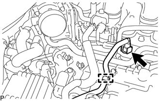
DISCONNECT INLET HEATER WATER HOSE
-
Remove the water hose set.
-
Disconnect the inlet heater water hose.
-
-
DISCONNECT OUTLET HEATER WATER HOSE
-
Remove the water hose set.
-
Disconnect the outlet heater water hose.
-
-
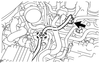
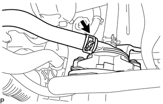
DISCONNECT AIR CONDITIONING HARNESS
-
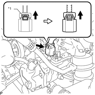
Text in Illustration *1 Green-colored Lock Release the green-colored lock and disconnect the connector as shown in the illustration.
CAUTION:
Wear insulated gloves when performing the procedure.
Note
Insulate the connector by sealing it with tape.
-
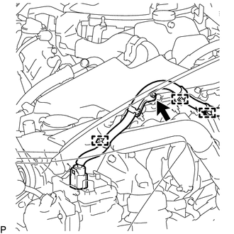
Remove the bolt and 3 wire harness clamps to disconnect the air conditioning harness.
-
-
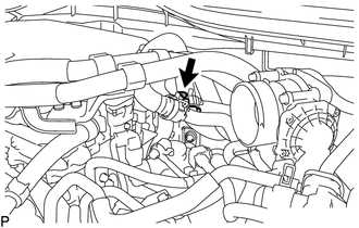
DISCONNECT NO. 2 OIL COOLER INLET HOSE
-
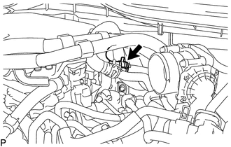
DISCONNECT NO. 2 OIL COOLER OUTLET HOSE
-
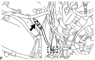
DISCONNECT NO. 5 INVERTER COOLING HOSE (for LHD)
-
Disconnect the No. 5 inverter cooling hose.
-
-
DISCONNECT NO. 2 MOTOR COOLING HOSE (for RHD)
-
Disconnect the No. 2 motor cooling hose.
-
-
REMOVE NO. 1 INVERTER COOLING PIPE (for LHD)
-
Disconnect the 2 connectors, 2 wire harness clamps and wire harness.
-
Remove the bolt and disconnect the 2 hoses to remove the No. 1 inverter cooling pipe.
-
-
DISCONNECT NO. 7 INVERTER COOLING HOSE (for RHD)
-
Disconnect the No. 7 inverter cooling hose.
-
-
DISCONNECT NO. 1 COOLER REFRIGERANT DISCHARGE HOSE
-
DISCONNECT SUCTION HOSE
-
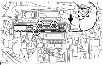
REMOVE ECM
-
DISCONNECT MOTOR CABLE
-
DISCONNECT GENERATOR CABLE
-
REMOVE INVERTER RESERVOIR TANK ASSEMBLY (for LHD)
-
REMOVE INVERTER RESERVOIR TANK ASSEMBLY (for RHD)
-
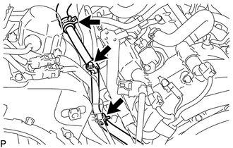
DISCONNECT ENGINE WIRE
-
Engine Room LH Side:
-
Remove the No. 1 engine room relay block cover.
-
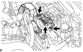
Disconnect the 3 connectors from the No. 2 connector holder.
-
Detach the clamp and 3 claws, and then disconnect the No. 2 connector holder.
-
-
Engine Room RH Side:
-
Remove the bolt, clamp and No. 3 engine wire.
-
-
-
REMOVE NO. 1 REAR FLOOR BOARD SUB-ASSEMBLY
-
REMOVE NO. 2 REAR FLOOR BOARD SUB-ASSEMBLY
-
REMOVE FRONT CENTER FLOOR BRACE
-
DISCONNECT HEATED OXYGEN SENSOR (for Bank 1 Sensor 2)
-
DISCONNECT HEATED OXYGEN SENSOR (for Bank 2 Sensor 2)
-
REMOVE FRONT EXHAUST PIPE ASSEMBLY
-
REMOVE NO. 1 EXHAUST PIPE SUPPORT BRACKET SUB-ASSEMBLY
-
REMOVE FRONT CENTER FLOOR BRACE SUB-ASSEMBLY
-
Remove the 4 bolts and front center floor brace sub-assembly.
-
-
REMOVE NO. 1 FUEL TANK PROTECTOR
-
REMOVE FRONT NO. 1 FLOOR HEAT INSULATOR
-
REMOVE PROPELLER WITH CENTER BEARING SHAFT ASSEMBLY
-
DISCONNECT STEERING SLIDING WITH SHAFT YOKE SUB-ASSEMBLY (w/o VGRS)
-
DISCONNECT STEERING SLIDING WITH SHAFT YOKE SUB-ASSEMBLY (w/ VGRS)
-
DISCONNECT FRONT SHOCK ABSORBER ASSEMBLY LH
-
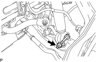
Remove the bolt and nut, and disconnect the lower part of the front shock absorber assembly LH from the front lower suspension arm assembly.
Note
When removing the bolt, keep the nut from rotating.
-
-
DISCONNECT FRONT SHOCK ABSORBER ASSEMBLY RH
Tech Tips
Remove the RH side following the same procedure as for the LH side.
-
DISCONNECT FRONT LOWER BALL JOINT ASSEMBLY LH
-
DISCONNECT FRONT LOWER BALL JOINT ASSEMBLY RH
Tech Tips
Remove the RH side following the same procedure as for the LH side.
-
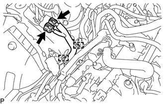
DISCONNECT POWER STEERING LINK WIRE HARNESS
-
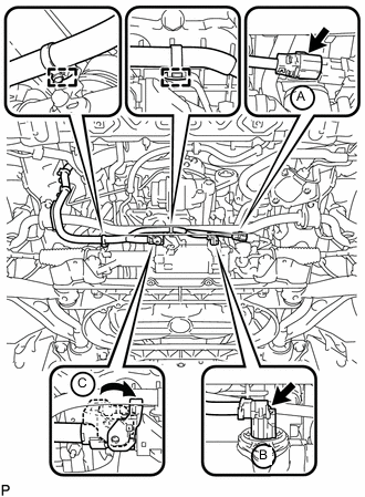
Disconnect the 2 wire harness clamps from the bracket.
-
Disconnect the 2 connectors (A) and (B) from the power steering link assembly.
-
Release the lock of connector (C) and disconnect the connector from the power steering link assembly.
-
-
DISCONNECT FLOOR SHIFT GEAR SHIFTING ROD SUB-ASSEMBLY
-
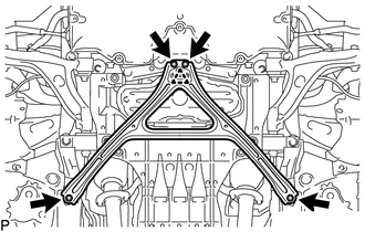
REMOVE FRONT NO. 2 UPPER SUSPENSION MEMBER
-
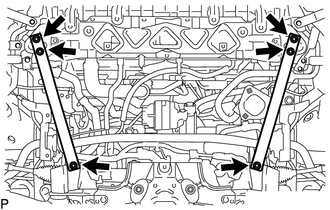
Remove the 6 bolts and front No. 2 upper suspension member.
-
-
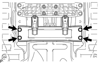
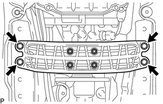
REMOVE FRONT LOWER SUSPENSION MEMBER PROTECTOR
-
Remove the 4 bolts and suspension member protector.
-
-
INSTALL ENGINE HANGER
-
Text in Illustration *1 No. 1 Engine Hanger *2 No. 2 Engine Hanger Install the 2 No. 1 engine hangers with the 4 bolts as shown in the illustration.
- Torque:
- 33 N*m { 337 kgf*cm, 24 ft.*lbf }
Tech Tips
No. 1 engine hanger 12281 - 31130 No. 2 engine hanger 12282 - 31140 Bolt 91671 - F0822
-
-
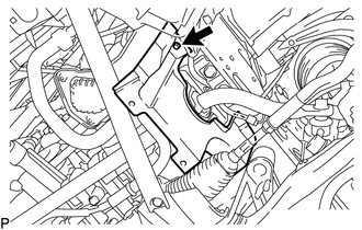
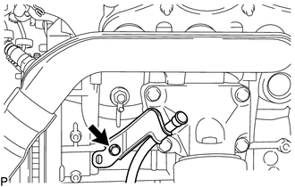
REMOVE ENGINE AND TRANSMISSION ASSEMBLY
-
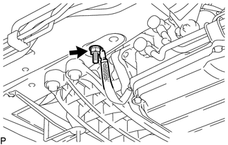
Remove the nut and disconnect the wire harness.
-
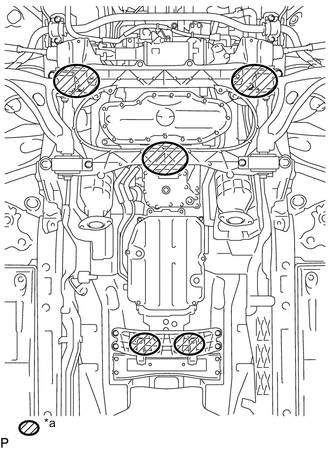
Text in Illustration *a Place Wooden Block or Plate Attachments Set the engine on an engine lifter.
Note
-
Place wooden blocks or plate lift attachments so that the engine is level.
-
With the exception of installing the engine assembly to an engine stand or removing the engine assembly from an engine stand, do not perform any work on the engine while it is suspended, as doing so is dangerous.
-
Never install attachments to the oil pan of the engine assembly or transmission as doing so may deform the oil pan.
-
-
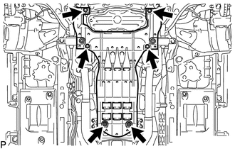
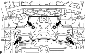
Remove the 4 bolts, and then disconnect the rear engine mounting member.
-
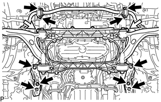
Remove the 10 bolts and 2 nuts shown in the illustration.
Text in Illustration 
Bolt 
Nut -
Operate the engine lifter, and then slowly remove the engine from the vehicle.
Note
-
Make sure the engine is clear of all wiring and hoses.
-
While lowering the engine from the vehicle, do not allow it to contact the vehicle.
-
-
Attach an engine sling device and hang the engine with a chain block.
Note
Pay attention to the angle of the sling device as the engine assembly or engine hangers may be damaged or deformed if the angle is incorrect.
-
-
REMOVE NO. 2 ENGINE OIL LEVEL DIPSTICK GUIDE
-
REMOVE ENGINE OIL LEVEL DIPSTICK GUIDE
-
Remove the bolt and engine oil level dipstick guide.
-
Remove the O-ring from the engine oil level dipstick guide.
-
-
REMOVE ENGINE UNDER COVER SUB-ASSEMBLY LH
-
Remove the engine under cover sub-assembly LH.
-
-
REMOVE ENGINE UNDER COVER SUB-ASSEMBLY RH
-
Remove the engine under cover sub-assembly RH.
-
-
REMOVE EXHAUST MANIFOLD SUB-ASSEMBLY LH
-
REMOVE EXHAUST MANIFOLD SUB-ASSEMBLY RH
-
REMOVE CONNECTOR
-
REMOVE WIRE HARNESS
-
REMOVE OIL COOLER HOSE TUBE SUB-ASSEMBLY
-
REMOVE WATER PIPE AND HOSE SUB-ASSEMBLY
-
REMOVE TRANSMISSION BREATHER HOSE SUB-ASSEMBLY
-
SUPPORT HYBRID VEHICLE TRANSMISSION ASSEMBLY
-
REMOVE STARTER HOLE INSULATOR
-
REMOVE FLYWHEEL HOUSING SIDE COVER
-
REMOVE HYBRID VEHICLE TRANSMISSION ASSEMBLY
-
REMOVE TRANSMISSION INPUT DAMPER COVER ASSEMBLY
-
REMOVE FLYWHEEL SUB-ASSEMBLY
-
REMOVE COMPRESSOR WITH MOTOR ASSEMBLY
-
REMOVE FAN AND GENERATOR V BELT
-
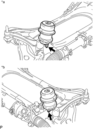
REMOVE FRONT SUSPENSION CROSSMEMBER SUB-ASSEMBLY
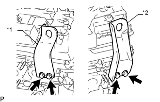
-
Text in Illustration *a LH Side *b RH Side Remove the 2 bolts, and then disconnect the front suspension crossmember sub-assembly from the engine.
-
-
INSTALL ENGINE ON ENGINE STAND
-
Install the engine to an engine stand with bolts.
Note
-
Pay attention to the angle of the sling device as the engine assembly or engine hangers may be damaged or deformed if the angle is incorrect.
-
With the exception of installing the engine assembly to an engine stand or removing the engine assembly from an engine stand, do not perform any work on the engine while it is suspended, as doing so is dangerous.
-
-
Remove the 4 bolts and 2 engine hangers.
-
-
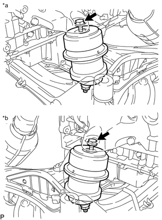
REMOVE FRONT ENGINE MOUNTING INSULATOR
Tech Tips
Only perform this procedure when replacement of the engine mounting insulator is necessary.
-
Text in Illustration *a LH Side *b RH Side Remove the 2 nuts and front engine mounting insulator RH and LH.
-
-
REMOVE REAR ENGINE MOUNTING MEMBER
-
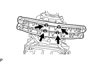
Remove the 4 nuts and rear engine mounting member from the rear No. 1 engine mounting insulator.
-
-
REMOVE REAR NO. 1 ENGINE MOUNTING INSULATOR
Tech Tips
Only perform this procedure when replacement of the engine mounting insulator is necessary.
-
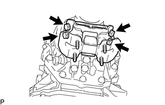
Remove the 4 bolts and rear No. 1 engine mounting insulator from the hybrid vehicle transmission assembly.
-