CAMSHAFT INSTALLATION
CAUTION / NOTICE / HINT
Tech Tips
Perform "Inspection After Repairs" after replacing the camshaft (intake or exhaust side) or camshaft timing gear assembly (intake or exhaust side) Click here.
PROCEDURE
-
INSTALL CAMSHAFT TIMING GEAR ASSEMBLY
Tech Tips
Perform "Inspection After Repairs" after replacing the camshaft timing gear assembly Click here.
-
Clamp the camshaft in a vise.
Note
Be careful not to damage the camshaft in the vise.
-
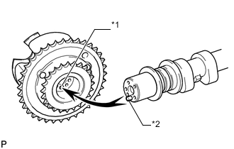
Text in Illustration *1 Pin Hole *2 Straight Pin Put the camshaft timing gear assembly and camshaft together by aligning the pin hole and straight pin.
-
Lightly press and turn the camshaft timing gear assembly against the camshaft, and press harder after the pin enters the hole.
Note
Be sure not to turn the camshaft timing gear assembly in the retard direction.
-
Check that there is no clearance between the camshaft timing gear assembly flange and camshaft.
-
Install the flange bolt while holding the camshaft.
- Torque:
- 100 N*m { 1020 kgf*cm, 74 ft.*lbf }
-
Check the lock of the camshaft timing gear assembly.
-
Secure the camshaft in place and confirm that the camshaft timing gear assembly is locked.
Note
Be careful not to damage the camshaft.
-
-
-
INSTALL CAMSHAFT TIMING EXHAUST GEAR ASSEMBLY
Tech Tips
Perform "Inspection After Repairs" after replacing the camshaft timing exhaust gear assembly Click here.
-
Clamp the camshaft in a vise.
Note
Be careful not to damage the camshaft in the vise.
-
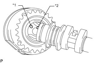
Text in Illustration *1 Pin Hole *2 Straight Pin Put the camshaft timing exhaust gear assembly and camshaft together by aligning the pin hole and straight pin.
-
Lightly press and turn the camshaft timing gear assembly against the camshaft, and press harder after the pin enters the hole.
Note
Be sure not to turn the camshaft timing exhaust gear in the advanced direction.
-
Check that there is no clearance between the gear flange and camshaft.
-
Install the flange bolt while holding the camshaft.
- Torque:
- 100 N*m { 1020 kgf*cm, 74 ft.*lbf }
-
Check the camshaft timing exhaust gear lock.
-
Make sure that the camshaft timing exhaust gear assembly locks.
-
-
-
INSTALL NO. 3 CAMSHAFT SUB-ASSEMBLY
Tech Tips
Perform "Inspection After Repairs" after replacing the No. 3 camshaft sub-assembly Click here.
-
Check that the notch is aligned with the "0" timing mark of the timing chain cover.
-
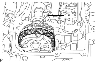
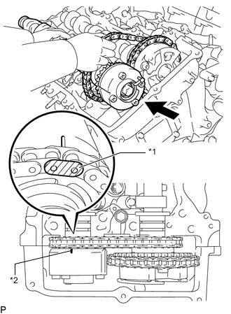
Text in Illustration *1 Timing Mark *2 Mark Plate (yellow) Align the mark plate (yellow) with the timing mark of the camshaft timing gear as shown in the illustration and install the No. 2 chain to the camshaft timing gear.
-
Clean the camshaft housing LH and camshaft journals, and apply engine oil to them.
-
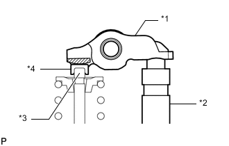
Text in Illustration *1 Valve Rocker Arm *2 Lash Adjuster *3 Valve Stem *4 Valve Stem Cap Make sure that the No. 1 valve rocker arm sub-assembly is installed as shown in the illustration.
-
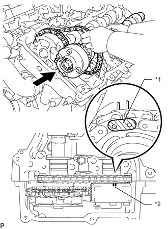
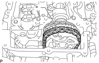
Text in Illustration *a Place on camshaft timing gear Install the chain to the No. 3 camshaft, and then install the camshaft to the camshaft housing LH.
Tech Tips
-
Place the chain on the camshaft timing gear but do not engage the teeth of the sprocket and the chain.
-
Install the camshaft so that the timing mark is facing upward.
-
-
-
INSTALL NO. 4 CAMSHAFT SUB-ASSEMBLY
Tech Tips
Perform "Inspection After Repairs" after replacing the No. 4 camshaft sub-assembly Click here.
-
Clean the camshaft housing LH and camshaft journals, and apply engine oil to them.
-
Text in Illustration *1 Mark Plate (yellow) *2 Timing Mark Pass the No. 4 camshaft through the No. 2 chain from the front of the vehicle, align the mark plate (yellow) with the timing mark and install the No. 2 chain to the camshaft timing exhaust gear.
-
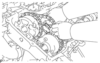
While lifting up the No. 4 camshaft, pass the No. 3 chain tensioner through the No. 2 chain and set it in place.
-
Install the No. 4 camshaft to the camshaft housing LH, and then install the No. 3 chain tensioner with the bolt.
- Torque:
- 21 N*m { 214 kgf*cm, 15 ft.*lbf }
-
-
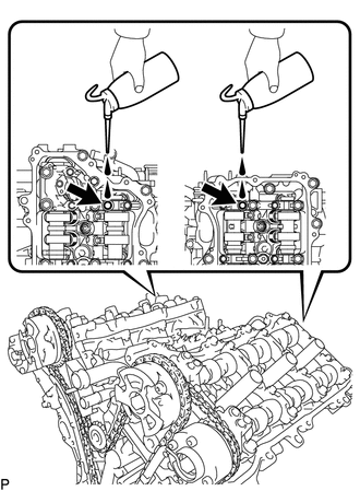
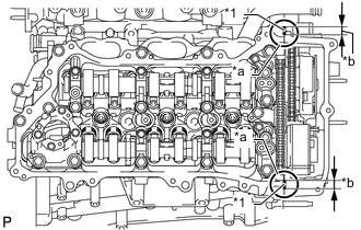
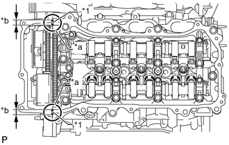
INSTALL CAMSHAFT BEARING CAP (for Bank 2)
-
Clean the camshaft bearing caps and apply engine oil to them.
-
Text in Illustration *1 Valve Rocker Arm *2 Lash Adjuster *3 Valve Stem *4 Valve Stem Cap Make sure that the No. 1 valve rocker arm sub-assembly is installed as shown in the illustration.
-
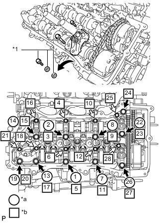
Text in Illustration *1 Service Bolts and Washers (used to temporarily secure the camshaft housing) *a Remove the service bolts and washers used to temporarily secure the camshaft housing *b Part to be installed 
Bolt A 
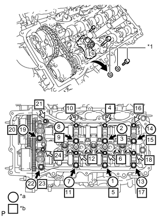
Bolt B Check the marks and numbers on the camshaft bearing caps, and then remove the service bolts and washers in the order shown in the illustration. Immediately after removing the service bolts and washers in the locations for the bearing caps, install the bearing caps with the bolts in the order shown in the illustration.
- Torque:
- for bolt A
- 28 N*m { 286 kgf*cm, 21 ft.*lbf }
- for bolt B
- 16 N*m { 163 kgf*cm, 12 ft.*lbf }
Note
-
Be sure to follow the numerical order when performing this procedure.
-
Do not drop the service bolts and washers into the cylinder head.
-
Check the torque of each bolt again.
-
-
INSTALL CHAIN SUB-ASSEMBLY
-
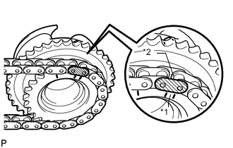
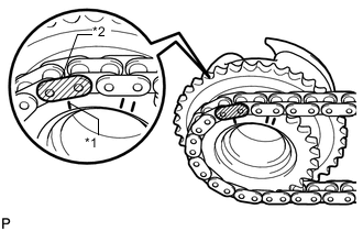
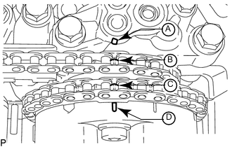
Text in Illustration *1 Paint Mark Align the paint marks on the camshaft timing gear and No. 1 chain, and install the No. 1 chain to the camshaft timing gear.
Tech Tips
If the paint marks are not aligned, align them by turning the camshaft slightly.
-
-
INSTALL CAMSHAFT
Tech Tips
Perform "Inspection After Repairs" after replacing the camshaft Click here.
-
Text in Illustration *a 5 to 10° Turn the crankshaft clockwise until it is in the position shown in the illustration so that the chain can be installed easily.
Tech Tips
When turning the crankshaft, engine oil may spray out of the oil holes.
-
Text in Illustration *1 Timing Mark *2 Mark Plate (yellow) Align the mark plate (yellow) with the timing mark of the camshaft timing gear as shown in the illustration and install the No. 2 chain to the camshaft timing gear.
-
Clean the camshaft housing RH and camshaft journals and apply engine oil to them.
-
Text in Illustration *1 Valve Rocker Arm *2 Lash Adjuster *3 Valve Stem *4 Valve Stem Cap Make sure that the No. 1 valve rocker arm sub-assembly is installed as shown in the illustration.
-
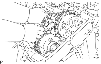
Text in Illustration *a Place on camshaft timing gear Install the chain to the camshaft, and then install the camshaft to the camshaft housing RH.
Tech Tips
-
Place the chain on the camshaft timing gear but do not engage the teeth of the sprocket and the chain.
-
Install the camshaft so that the timing mark is facing upward.
-
-
-
INSTALL NO. 2 CAMSHAFT
Tech Tips
Perform "Inspection After Repairs" after replacing the No. 2 camshaft Click here.
-
Clean the camshaft housing RH and camshaft journals, and apply engine oil to them.
-
Text in Illustration *1 Mark Plate (yellow) *2 Timing Mark Pass the No. 2 camshaft through the No. 2 chain from the front of the vehicle, align the mark plate (yellow) with the timing mark and install the No. 2 chain to the camshaft timing exhaust gear.
-
While lifting up the No. 2 camshaft, pass the No. 2 chain tensioner through the No. 2 chain and set it in place.
-
Install the No. 2 camshaft to the camshaft housing RH, and then install the No. 2 chain tensioner with the bolt.
- Torque:
- 21 N*m { 214 kgf*cm, 15 ft.*lbf }
-
-
INSTALL CAMSHAFT BEARING CAP (for Bank 1)
-
Clean the camshaft bearing caps and apply engine oil to them.
-
Text in Illustration *1 Valve Rocker Arm *2 Lash Adjuster *3 Valve Stem *4 Valve Stem Cap Make sure that the No. 1 valve rocker arm sub-assembly is installed as shown in the illustration.
-
Text in Illustration *1 Service Bolt and Washers (used to temporarily secure the camshaft housing) *a Remove the service bolts and washers to temporarily secure the camshaft housing *b Part to be installed Bolt A Bolt B Check the marks and numbers on the camshaft bearing caps, and then remove the service bolts and washers in the order shown in the illustration. Immediately after removing the service bolts and washers in the locations for the bearing caps, install the bearing caps with the bolts in the order shown in the illustration.
- Torque:
- for bolt A
- 28 N*m { 286 kgf*cm, 21 ft.*lbf }
- for bolt B
- 16 N*m { 163 kgf*cm, 12 ft.*lbf }
Note
-
Be sure to follow the numerical order when performing this procedure.
-
Do not drop the service bolts and washers into the cylinder head.
-
Check the torque of each bolt again.
-
-
INSTALL CHAIN SUB-ASSEMBLY
-
Text in Illustration *1 Paint Mark Align the paint marks on the camshaft timing gear and chain, and install the chain to the camshaft timing gear.
Tech Tips
If the paint marks are not aligned, align them by turning the camshaft slightly.
-
-
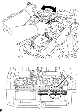
INSTALL NO. 1 CHAIN TENSIONER ASSEMBLY
-
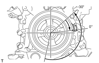
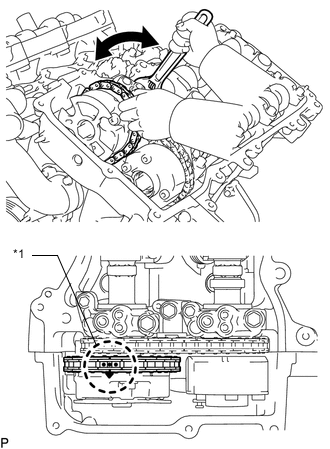
Turn the crankshaft counterclockwise 30° past the "0" timing mark, and then turn it clockwise to align the notch with the "0" timing mark.
-
Turn the crankshaft slightly to eliminate the slack in the chain.
Tech Tips
Make sure there is some slack in the chain around the area where the chain tensioner is installed.
-
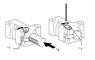
Text in Illustration *1 Stopper Plate *a Push While turning the stopper plate of the tensioner clockwise, push in the plunger of the tensioner as shown in the illustration.
-
While turning the stopper plate of the tensioner counterclockwise, insert a pin of 1.27 mm (0.0500 in.) diameter into the holes in the stopper plate and tensioner to secure the stopper plate in place.
-
Install the No. 1 chain tensioner with the 2 bolts.
- Torque:
- 10 N*m { 102 kgf*cm, 7 ft.*lbf }
-
Remove the pin from the No. 1 chain tensioner.
-
-
INSPECT VALVE TIMING
-
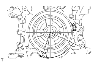
Check the camshaft timing marks.
Note
-
Check each timing mark from a viewpoint directly in line with the center of the camshaft and the timing mark on each camshaft timing gear.
-
If the timing marks are checked from any other viewpoint, the valve timing may appear misaligned.
-
-
Check that each camshaft timing mark is positioned as shown in the illustration.

Text in Illustration *1 Timing Mark - - *a Viewpoint - - Tech Tips
For Intake Camshaft: Be sure to check mark A at the point when marks B, C and D are positioned in line. If the marks are checked from any other viewpoint, they cannot be checked correctly.
-
If the valve timing is misaligned, reinstall the timing chain.
-
Turn the crankshaft 2 revolutions, set the No. 1 cylinder to TDC/compression and check the timing marks again.
-
-
INSTALL TIMING CHAIN COVER PLATE
-
Install a new gasket and the timing chain cover plate with the 4 bolts.
- Torque:
- 9.1 N*m { 93 kgf*cm, 81 in.*lbf }
-
-
INSTALL SPARK PLUG TUBE GASKET
-
POUR ENGINE OIL
Tech Tips
Before installing the cylinder head cover, pour engine oil into the locations shown in the illustration.
-
INSTALL CYLINDER HEAD COVER SUB-ASSEMBLY
-
Before applying seal packing black, completely remove any old seal packing adhering to the sealed areas.
-
Text in Illustration *1 Seal Packing Black Application Area *a Part Contact Areas *b 4.0 to 10.0 mm (0.157 to 0.394 in.) Clean and degrease the areas where the cylinder head cover, timing chain cover and camshaft housing RH contact each other with brake cleaner or non-residue solvent so that there is no oil, water or other foreign matter adhering to those areas.
Note
The seal packing black cannot be wiped off. It can only be removed with a scraper.
-
Apply seal packing black (diameter: 2.0 to 3.0 mm (0.0787 to 0.118 in.)) to the areas shown in the illustration and install the cylinder head cover.
Seal packing Toyota Genuine Seal Packing Black, Three Bond 1207B or equivalent Note
-
Remove any oil from the contact surface.
-
Install the cylinder head cover within 3 minutes after applying seal packing.
-
Do not start the engine for at least 2 hours after installation.
-
-
Install 5 new gaskets to the camshaft bearing caps.
-
Install a new gasket to the cylinder head cover.
-
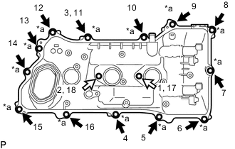
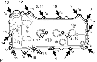
Text in Illustration *a Apply adhesive to these bolts Bolt A Bolt B Apply adhesive to the threads of the 13 bolts shown in the illustration, and then using 2 new seal washers for each bolt, install the cylinder head cover with the 15 bolts.
- Torque:
- 10 N*m { 102 kgf*cm, 7 ft.*lbf }
Adhesive Toyota Genuine Adhesive 1324, Three Bond 1324 or equivalent. Standard Bolt Item Length A 25 mm (0.984 in.) B 60 mm (2.36 in.) -
Attach the clamps and connect the connectors to connect the cylinder head cover.
-
-
INSTALL CYLINDER HEAD COVER SUB-ASSEMBLY LH
-
Before applying seal packing black, completely remove any old seal packing adhering to the sealed areas.
-
Text in Illustration *1 Seal Packing Black Application Area *a Part Contact Areas *b 4.0 to 10.0 mm (0.157 to 0.394 in.) Clean and degrease the areas where the cylinder head cover LH, timing chain cover and camshaft housing LH contact each other with brake cleaner or non-residue solvent so that there is no oil, water or other foreign matter adhering to those areas.
Note
The seal packing black cannot be wiped off. It can only be removed with a scraper.
-
Apply seal packing black (diameter: 2.0 to 3.0 mm (0.0787 to 0.118 in.)) to the areas shown in the illustration and install the cylinder head cover LH.
Seal packing Toyota Genuine Seal Packing Black, Three Bond 1207B or equivalent Note
-
Remove any oil from the contact surface.
-
Install the cylinder head cover LH within 3 minutes after applying seal packing.
-
Do not start the engine for at least 2 hours after installation.
-
-
Install 5 new gaskets to the camshaft bearing caps.
-
Install a new gasket to the cylinder head cover.
-
Text in Illustration *a Apply adhesive to these bolts Bolt A Bolt B 
Bolt C 
Bolt D Apply adhesive to the threads of the 14 bolts shown in the illustration, and then using 2 new seal washers for each bolt, install the cylinder head cover LH with the 16 bolts.
- Torque:
- for bolt A and B
- 21 N*m { 214 kgf*cm, 15 ft.*lbf }
- for bolt C and D
- 10 N*m { 102 kgf*cm, 7 ft.*lbf }
Adhesive Toyota Genuine Adhesive 1324, Three Bond 1324 or equivalent. Standard Bolt Item Length A 25 mm (0.984 in.) B 60 mm (2.36 in.) C 35 mm (1.38 in.) D 70 mm (2.76 in.) -
Attach the clamps and connect the connectors to connect the cylinder head cover LH.
-
-
INSTALL NO. 2 OIL LEVEL DIPSTICK GUIDE
-
INSTALL SPARK PLUG
-
INSTALL IGNITION COIL ASSEMBLY
-
CONNECT NO. 2 WATER BY-PASS PIPE SUB-ASSEMBLY
-
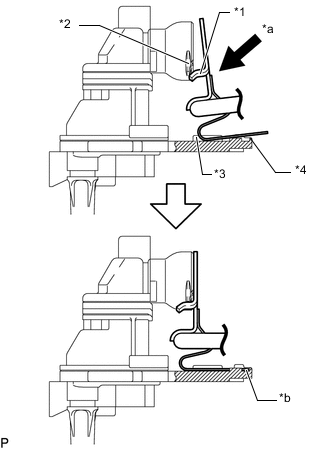
Text in Illustration *1 Pipe Claw *2 Separator Connection Point *3 Separator Guide Rail *4 Separator Stopper *a Insert at an angle *b Insert until stay contacts stopper While keeping the pipe stay aligned with the guide rail of the separator, push the stay in downwards at an angle until the stay contacts the stopper as shown in the illustration, and then connect the No. 2 water by-pass pipe sub-assembly and install the bolt.
- Torque:
- 10 N*m { 102 kgf*cm, 7 ft.*lbf }
Note
-
Make sure the pipe claw does not come off the separator connection point.
-
When replacing the separator, also replace the pipe.
-
-
INSTALL PCV VALVE SUB-ASSEMBLY
-
INSTALL ENGINE COVER
-
INSTALL INJECTOR DRIVER
-
INSTALL NO. 1 ENGINE COVER
-
INSTALL FUEL PUMP ASSEMBLY
-
INSTALL ECM
-
INSTALL INVERTER WITH CONVERTER ASSEMBLY