ENGINE UNIT DISASSEMBLY

PROCEDURE
-
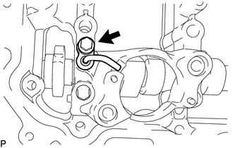
REMOVE NO. 4 WATER BY-PASS PIPE
-
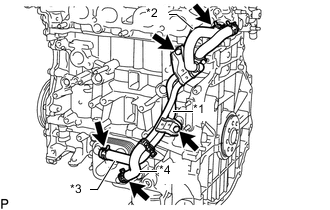
Text in Illustration *1 No. 4 Water By-pass Pipe *2 No. 9 Water By-pass Hose *3 No. 7 Water By-pass Hose *4 No. 8 Water By-pass Hose Slide the clip and disconnect the No. 9 water by-pass hose from the cylinder head sub-assembly.
-
Slide the 2 clips and disconnect the No. 7 water by-pass hose and No. 8 water by-pass hose from the oil cooler assembly.
-
Remove the 2 bolts and No. 4 water by-pass pipe.
-
-
REMOVE SPARK PLUG
-
REMOVE KNOCK CONTROL SENSOR
-
REMOVE ENGINE OIL PRESSURE SWITCH ASSEMBLY
-
REMOVE CAMSHAFT TIMING OIL CONTROL VALVE ASSEMBLY
-
REMOVE VVT SENSOR
-
REMOVE PCV VALVE SUB-ASSEMBLY
-
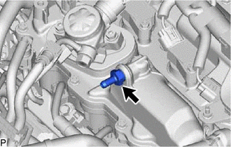
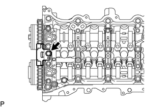
Using a 19 mm deep socket wrench, remove the PCV valve sub-assembly.
-
-
REMOVE OIL FILLER CAP SUB-ASSEMBLY
-
Remove the oil filler cap sub-assembly from the cylinder head cover sub-assembly.
-
-
REMOVE OIL FILLER CAP GASKET
-
Remove the oil filler cap gasket from the oil filler cap sub-assembly.
-
-
REMOVE CYLINDER HEAD COVER SUB-ASSEMBLY
-
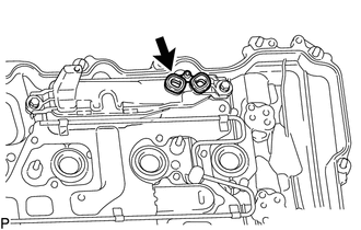
REMOVE PCV CASE SUB-ASSEMBLY
-
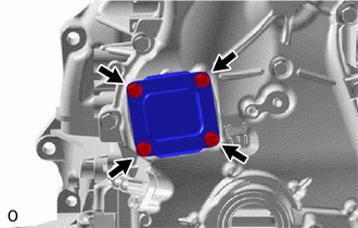
Remove the gasket from the PCV case sub-assembly.
-
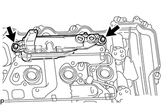
Remove the 2 bolts and PCV case sub-assembly from the cylinder head cover sub-assembly.
-
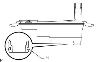
Text in Illustration *1 O-ring Remove the O-ring from the PCV case sub-assembly.
-
-
REMOVE SPARK PLUG TUBE GASKET
-
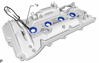
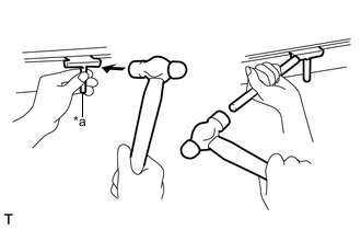
Text in Illustration *a Protective Tape Using a screwdriver, pry out the 4 spark plug tube gaskets.
Note
Be careful not to damage the cylinder head cover sub-assembly.
Tech Tips
Tape the screwdriver tip before use.
-
-
REMOVE CRANKSHAFT POSITION SENSOR
-
REMOVE CRANKSHAFT PULLEY ASSEMBLY
-
REMOVE TIMING CHAIN COVER ASSEMBLY
-
REMOVE TIMING CHAIN COVER PLATE
-
Remove the 4 bolts, timing chain cover plate and No. 1 timing belt cover gasket from the timing chain cover assembly.
-
-
REMOVE TIMING GEAR CASE OR TIMING CHAIN CASE OIL SEAL
-
SET NO. 1 CYLINDER TO TDC/COMPRESSION
-
Temporarily install the crankshaft pulley set bolt.
-
Rotate the crankshaft clockwise so that the timing marks on the crankshaft timing gear or sprocket and camshaft timing gears are positioned as shown in the illustration.
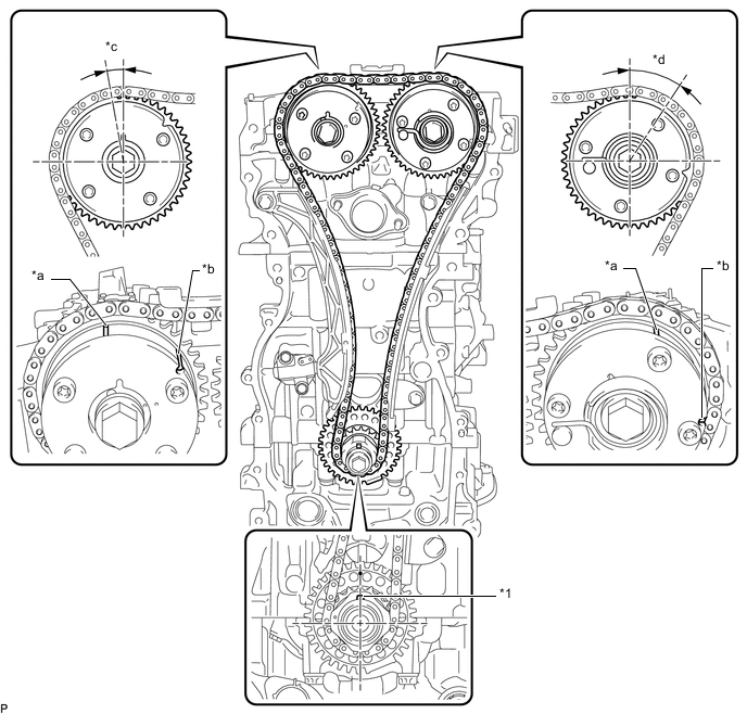
Text in Illustration *1 Crankshaft Pulley Set Crankshaft Key - - *a Timing Mark *b Identification Groove *c Approximately 7° *d Approximately 32° Tech Tips
-
The camshaft timing gear assembly and the camshaft timing exhaust gear assembly have both timing marks and identification grooves. Use the timing marks for alignment.
-
If the timing marks do not align, rotate the crankshaft clockwise again and align the timing marks.
-
-
Remove the crankshaft pulley set bolt.
-
-
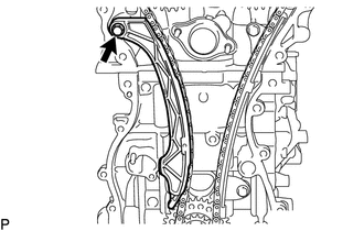
REMOVE TIMING CHAIN GUIDE
-
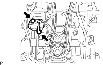
Remove the bolt and timing chain guide.
-
-
REMOVE NO. 1 CHAIN TENSIONER ASSEMBLY
-
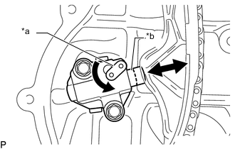
Text in Illustration *a Stopper Plate *b Plunger Allow the plunger to extend slightly, and then rotate the stopper plate counterclockwise to release the lock. Once the lock is released, push the plunger into the tensioner.
-
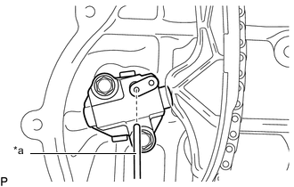
Text in Illustration *a Pin Move the stopper plate clockwise to set the lock, and insert a pin into the stopper plate hole.
-
Remove the 2 bolts, No. 1 chain tensioner assembly and chain tensioner gasket.
-
-
REMOVE CHAIN TENSIONER SLIPPER
-
Remove the bolt and chain tensioner slipper.
-
-
REMOVE NO. 1 CHAIN VIBRATION DAMPER
-
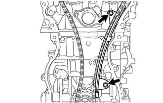
Remove the 2 bolts and No. 1 chain vibration damper.
-
-
REMOVE CHAIN SUB-ASSEMBLY
-
Remove the chain sub-assembly.
-
-
REMOVE CRANKSHAFT TIMING GEAR OR SPROCKET
-
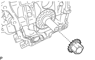
Remove the crankshaft timing gear or sprocket from the crankshaft.
-
-
REMOVE CRANKSHAFT PULLEY SET CRANKSHAFT KEY
-
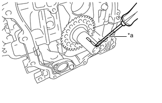
Text in Illustration *a Protective Tape Using a screwdriver, remove the 2 crankshaft pulley set crankshaft keys from the crankshaft.
Tech Tips
Tape the screwdriver tip before use.
-
-
REMOVE CAMSHAFT TIMING GEAR ASSEMBLY
-
REMOVE CAMSHAFT TIMING EXHAUST GEAR ASSEMBLY
-
REMOVE OIL PIPE SUB-ASSEMBLY
-
Remove the bolt and oil pipe sub-assembly from the No. 4 camshaft bearing cap.
-
-
REMOVE CAMSHAFT HOUSING SUB-ASSEMBLY
-
REMOVE CAMSHAFT BEARING CAP
-
REMOVE OIL CONTROL VALVE FILTER
-
REMOVE NO. 1 CAMSHAFT BEARING
-
REMOVE CAMSHAFT
-
REMOVE NO. 2 CAMSHAFT
-
REMOVE NO. 2 CAMSHAFT BEARING
-
REMOVE NO. 1 VALVE ROCKER ARM SUB-ASSEMBLY
-
REMOVE VALVE LASH ADJUSTER ASSEMBLY
-
REMOVE VALVE STEM CAP
-
REMOVE CYLINDER HEAD SUB-ASSEMBLY
-
REMOVE CYLINDER HEAD GASKET
-
REMOVE CYLINDER BLOCK WATER JACKET SPACER
-
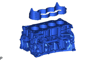
Remove the cylinder block water jacket spacer from the cylinder block sub-assembly.
Note
Be sure to remove the water jacket spacer. If it is not removed, it may fall and become damaged when the cylinder block sub-assembly is inverted.
-
-
REMOVE OIL FILTER CAP ASSEMBLY
-
REMOVE ENGINE OIL LEVEL SENSOR
-
REMOVE OIL COOLER ASSEMBLY
-
REMOVE OIL PAN DRAIN PLUG
-
Remove the oil pan drain plug and gasket from the oil pan sub-assembly.
-
-
REMOVE OIL PAN SUB-ASSEMBLY
-
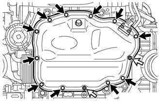
Remove the 11 bolts and 2 nuts.
Text in Illustration 
Bolt 
Nut -
Text in Illustration *a Oil Pan Seal Cutter Insert the blade of an oil pan seal cutter between the oil pan sub-assembly and stiffening crankcase assembly, cut off the applied sealer and remove the oil pan sub-assembly.
Note
-
Be careful not to damage the contact surface of the stiffening crankcase assembly and oil pan sub-assembly.
-
Be careful not to damage the oil pan sub-assembly flange.
Tech Tips
Be sure to clean the bolts and stud bolts and check the threads for cracks or other damage.
-
-
-
REMOVE OIL STRAINER SUB-ASSEMBLY
-
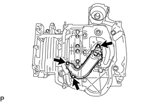
Remove the 3 bolts, oil strainer sub-assembly and gasket.
-
-
REMOVE NO. 1 OIL PAN BAFFLE PLATE
-
Remove the 4 bolts and No. 1 oil pan baffle plate.
-
-
REMOVE ENGINE BALANCER ASSEMBLY
-
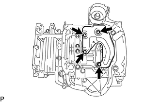
Remove the 5 bolts and engine balancer assembly.
Note
Do not disassemble the engine balancer assembly.
-
-
REMOVE STIFFENING CRANKCASE ASSEMBLY
-
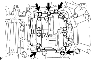
Remove the 7 bolts.
-
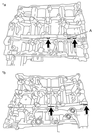
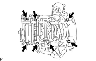
Text in Illustration *a LH Side *b RH Side Using a screwdriver, remove the stiffening crankcase assembly by prying between the stiffening crankcase assembly and cylinder block sub-assembly at the places shown in the illustration.
Note
-
Do not pry section A in the illustration. Otherwise, the stiffening case assembly may be damaged.
-
Be careful not to damage the contact surfaces of the cylinder block sub-assembly and stiffening crankcase assembly.
Tech Tips
Tape the screwdriver tip before use.
-
-
-
REMOVE REAR ENGINE OIL SEAL
-
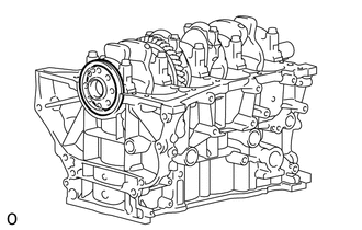
Remove the rear engine oil seal from the cylinder block sub-assembly.
-
-
REMOVE STUD BOLT
Note
If a stud bolt is deformed or its threads are damaged, replace it.
-
REMOVE CYLINDER HEAD SUB-ASSEMBLY
Note
If a ring pin is deformed or damaged, replace it.
-
REMOVE STRAIGHT PIN
Note
If a straight pin is deformed or damaged, replace it.