REAR CRANKSHAFT OIL SEAL INSTALLATION

PROCEDURE
-
INSTALL REAR ENGINE OIL SEAL
-
Apply MP grease to the lip of a new rear engine oil seal.
Note
-
Keep the lip free from foreign matter.
-
Do not allow MP grease to contact the dust seal.
-
-
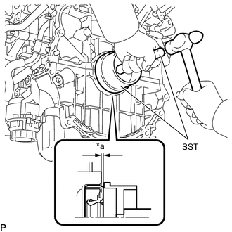
Text in Illustration *a Depth Using SST and a hammer, tap in the rear engine oil seal until its surface is flush with the edges of the cylinder block sub-assembly and stiffening crankcase assembly.
- SST
- 09223-15030
- 09950-70010 ( 09951-07150 )
Standard depth 0 to 0.9 mm (0 to 0.0354 in.) Note
-
Do not tap in the rear engine oil seal at an angle.
-
Keep the lip free from foreign matter.
-
Wipe off any MP grease from the crankshaft.
-
-
INSTALL FLYWHEEL SUB-ASSEMBLY
-
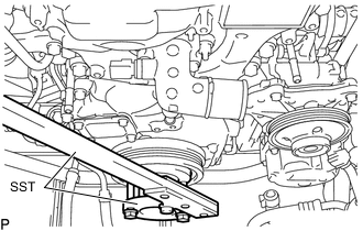
Using SST, hold the crankshaft.
- SST
- 09213-54015
- 09330-00021
Tech Tips
SST (Crankshaft pulley holding tool) fixing bolt part No.: 91551-80650 (2 pcs)
-
Clean the bolts and their installation bolt holes.
-
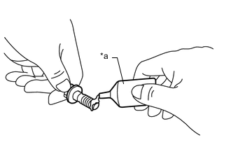
Text in Illustration *a Adhesive Apply a few drops of adhesive to 2 or 3 threads at the tip of the 8 bolts.
Adhesive Toyota Genuine Adhesive 1324, Three Bond 1324 or equivalent Note
Install the bolt within 3 minutes after applying adhesive.
-
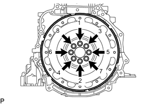
Install and uniformly tighten the 8 bolts in the sequence shown in the illustration.
- Torque:
- 130 N*m { 1326 kgf*cm, 96 ft.*lbf }
Note
-
Do not start the engine for at least an hour after installing the flywheel sub-assembly.
-
Make sure there is no foreign matter or oil on the flywheel sub-assembly.
-
-
INSTALL TRANSMISSION INPUT DAMPER ASSEMBLY
-
Using SST, hold the crankshaft.
- SST
- 09213-54015
- 09330-00021
Tech Tips
SST (Crankshaft pulley holding tool) fixing bolt part No.: 91551-80650 (2 pcs)
-
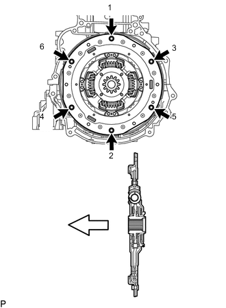
Install and uniformly tighten the 6 bolts in the sequence shown in the illustration.
- Torque:
- 30 N*m { 306 kgf*cm, 22 ft.*lbf }
Text in Illustration 
Engine Side Note
-
Make sure there is no oil on the transmission input damper assembly and the flywheel sub-assembly.
-
Make sure that the forward/backward direction of the transmission input damper assembly is correct before installation.
-
Do not allow grease to contact the splines of the transmission input damper assembly or the input shaft.
-
-
INSTALL HYBRID VEHICLE TRANSMISSION ASSEMBLY