HYBRID BATTERY SYSTEM, Diagnostic DTC:P0A9D-123, P0A9E-123, P0AC7-123, P0AC8-123, P0ACC-123, P0ACD-123, P0AEA-123, P0AEB-123, P0BC4-123, P0BC5-123
| DTC Code | DTC Name |
|---|---|
| P0A9D-123 | Hybrid Battery Temperature Sensor "A" Circuit Low |
| P0A9E-123 | Hybrid Battery Temperature Sensor "A" Circuit High |
| P0AC7-123 | Hybrid Battery Temperature Sensor "B" Circuit Low |
| P0AC8-123 | Hybrid Battery Temperature Sensor "B" Circuit High |
| P0ACC-123 | Hybrid Battery Temperature Sensor "C" Circuit Low |
| P0ACD-123 | Hybrid Battery Temperature Sensor "C" Circuit High |
| P0AEA-123 | Hybrid Battery Temperature Sensor "D" Circuit Low |
| P0AEB-123 | Hybrid Battery Temperature Sensor "D" Circuit High |
| P0BC4-123 | Hybrid Battery Temperature Sensor "E" Circuit Low |
| P0BC5-123 | Hybrid Battery Temperature Sensor "E" Circuit High |
DESCRIPTION
-
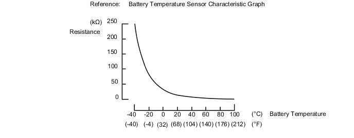
There are 2 battery temperature sensors located on the upper side of the upper HV battery and 3 battery temperature sensors located on the lower side of the lower HV battery. The resistance of the thermistor, which is built into each battery temperature sensor, varies in accordance with changes in the HV battery temperature. The lower the battery temperature, the higher the thermistor resistance. Conversely, the higher the temperature, the lower the resistance. The battery smart unit uses the battery temperature sensors to detect the HV battery temperature, and sends the detected value to the power management control ECU. Based on the results of this detection, the power management control ECU controls the blower fan. (The blower fan starts when HV battery temperature rises above a predetermined level.)
Temperature Sensor Identification Cross Reference Table DTC Title Sensor Battery Temperature Sensor GTS Display A 0 1 B 1 2 C 2 3 D 3 4 E 4 5 Tech Tips
For example, sensor A in the DTC title is battery temperature sensor (No. 0). This sensor is displayed as Temp of Batt TB1 in the Data List.
| DTC No. | INF Code | DTC Detection Condition | Trouble Area |
|---|---|---|---|
| P0A9D P0A9E P0AC7 P0AC8 P0ACC P0ACD P0AEA P0AEB P0BC4 P0BC5 |
123 | When the temperature of the battery temperature sensor is less than the standard value (open) or higher than the standard value (shorted) (1 trip detection). |
|
Tech Tips
After confirming that a DTC is output, use the GTS to check "Temp of BATT TB 1 to 5" in the hybrid vehicle control system ECU Data List.
| Temperature Displayed | Malfunction |
|---|---|
| Below -45°C (-49°F) | Open or +B short circuit |
| 95°C (203°F) or higher | GND short circuit |
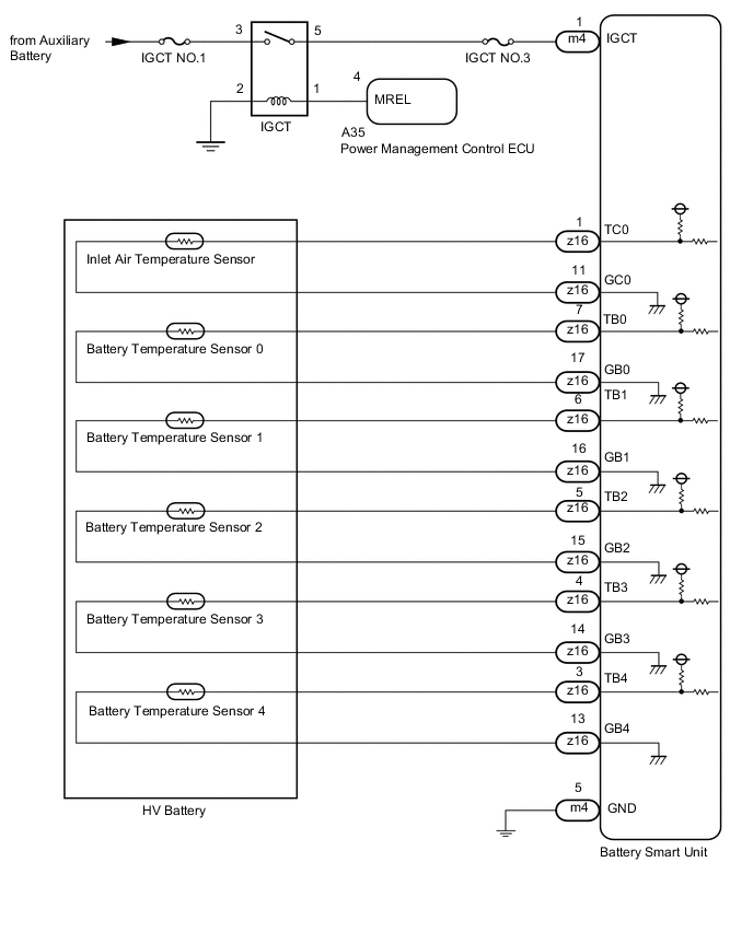
WIRING DIAGRAM
CAUTION / NOTICE / HINT
CAUTION:
-
Before inspecting the high-voltage system, take safety precautions to prevent electrical shocks, such as wearing insulated gloves and removing the service plug grip. After removing the service plug grip, put it in your pocket to prevent other technicians from accidentally reconnecting it while you are working on the high-voltage system.
-
After removing the service plug grip, wait at least 10 minutes before touching any of the high-voltage connectors or terminals. After waiting for 10 minutes, check the voltage at the terminals in the inspection point in the inverter with converter assembly. The voltage should be 0 V before beginning work Click here.
Tech Tips
At least 10 minutes is required to discharge the high-voltage capacitor inside the inverter with converter assembly.
-
When disposing of an HV battery, make sure to return it through an authorized collection agent who is capable of handling it safely. If the HV battery is returned via the manufacturer specified route, it will be returned properly and in a safe manner by an authorized collection agent.
Note
After turning the power switch off, waiting time may be required before disconnecting the cable from the negative (-) auxiliary battery terminal. Therefore, make sure to read the disconnecting the cable from the negative (-) auxiliary battery terminal notices before proceeding with work Click here.
PROCEDURE
-
CHECK FOR DTCS (HYBRID CONTROL)
-
Connect the GTS to the DLC3.
-
Turn the power switch on (IG).
-
Enter the following menus: Powertrain / Hybrid Control / Trouble Codes.
-
Read output DTCs.
Result Result Proceed to P0AFC-123 is not output. A P0AFC-123 is also output. B -
Turn the power switch off.
B 
GO TO DTC CHART (P0AFC-123) Click here
A 
-
-
READ VALUE USING GTS
-
Connect the GTS to the DLC3.
-
Turn the power switch on (IG).
-
Enter the following menus: Powertrain / Hybrid Control / Data List / Temp of Batt TB 1 to 5.
Tech Tips
Compare the temperature of the 5 battery temperature sensors to determine the sensor with the malfunction (Temp of Batt TB1 to TB5).
-
Turn the power switch off.
NEXT
-
-
CHECK CONNECTOR CONNECTION CONDITION (BATTERY TEMPERATURE SENSOR)
CAUTION:
Be sure to wear insulated gloves.
-
Check that the service plug grip is not installed.
Note
After removing the service plug grip, do not turn the power switch on (READY), unless instructed by the repair manual because this may cause a malfunction.
-
Remove the No. 4 hybrid vehicle battery carrier bracket sub-assembly Click here.
-
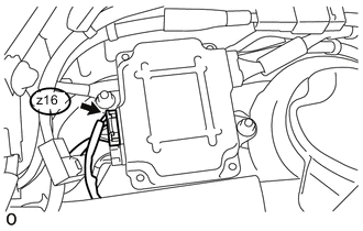
Check the connections of the connector of the battery smart unit Click here.
OK The connectors are connected securely and there are no contact problems. -
Install the No. 4 hybrid vehicle battery carrier bracket sub-assembly.
NG
CONNECT SECURELY
OK
-
-
CHECK HV BATTERY (BATTERY TEMPERATURE SENSOR)
CAUTION:
Be sure to wear insulated gloves.
-
Check that the service plug grip is not installed.
Note
After removing the service plug grip, do not turn the power switch on (READY), unless instructed by the repair manual because this may cause a malfunction.
-
Remove the No. 4 hybrid vehicle battery carrier bracket sub-assembly Click here.
-
Disconnect connectors from the battery smart unit.
-
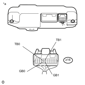
Text in Illustration *a Rear view of wire harness connector
(to Battery Smart Unit)
Measure the resistance according to the values in the table below.
Tester Connection Tester Connection Battery Temperature Sensor No. z16-7 (TB0) - z16-17 (GB0) 0 z16-6 (TB1) - z16-16 (GB1) 1 Standard Resistance Thermistor Temperature Switch Condition Specified Condition 0 °C (32 °F) Power switch off 26.7 to 27.8 kΩ 25 °C (77 °F) Power switch off 9.9 to 10.1 kΩ 40 °C (104 °F) Power switch off 5.73 to 5.92 kΩ -
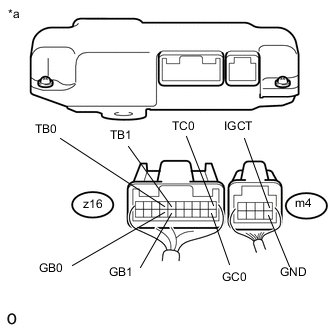
Text in Illustration *a Rear view of wire harness connector
(to Battery Smart Unit)
Measure the resistance according to the value(s) in the table below.
Standard Resistance Tester Connection Switch Condition Standard Resistance z16-7 (TB0) - m4-1 (IGCT) Power switch off 10 kΩ or higher z16-7 (TB0) - m4-5 (GND) Power switch off 10 kΩ or higher z16-17 (GB0) - m4-1 (IGCT) Power switch off 10 kΩ or higher z16-17 (GB0) - m4-5 (GND) Power switch off 10 kΩ or higher z16-6 (TB1) - m4-1 (IGCT) Power switch off 10 kΩ or higher z16-6 (TB1) - m4-5 (GND) Power switch off 10 kΩ or higher z16-16 (GB1) - m4-1 (IGCT) Power switch off 10 kΩ or higher z16-16 (GB1) - m4-5 (GND) Power switch off 10 kΩ or higher -
Measure the resistance according to the value(s) in the table below.
Standard Resistance Tester Connection Switch Condition Standard Resistance z16-1 (TC0) - m4-1 (IGCT) Power switch off 10 kΩ or higher z16-1 (TC0) - m4-5 (GND) Power switch off 10 kΩ or higher z16-11 (GC0) - m4-1 (IGCT) Power switch off 10 kΩ or higher z16-11 (GC0) - m4-5 (GND) Power switch off 10 kΩ or higher -
Connect the battery smart unit connectors.
-
Install the No. 4 hybrid vehicle battery carrier bracket sub-assembly.
NG 
CHECK HARNESS AND CONNECTOR (BATTERY TEMPERATURE SENSOR) Click here
OK
-
-
CHECK HV BATTERY (BATTERY TEMPERATURE SENSOR)
CAUTION:
Be sure to wear insulated gloves.
-
Check that the service plug grip is not installed.
Note
After removing the service plug grip, do not turn the power switch on (READY), unless instructed by the repair manual because this may cause a malfunction.
-
Remove the No. 4 hybrid vehicle battery carrier bracket sub-assembly Click here.
-
Disconnect connectors from the battery smart unit.
-
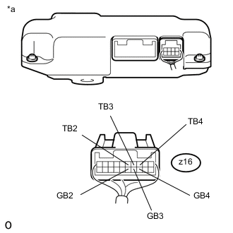
Text in Illustration *a Rear view of wire harness connector
(to Battery Smart Unit)
Measure the resistance according to the values in the table below.
Tester Connection Tester Connection Battery Temperature Sensor No. z16-5 (TB2) - z16-15 (GB2) 2 z16-4 (TB3) - z16-14 (GB3) 3 z16-3 (TB4) - z16-13 (GB4) 4 Standard Resistance Thermistor Temperature Switch Condition Specified Condition 0 °C (32 °F) Power switch off 26.7 to 27.8 kΩ 25 °C (77 °F) Power switch off 9.9 to 10.1 kΩ 40 °C (104 °F) Power switch off 5.73 to 5.92 kΩ -
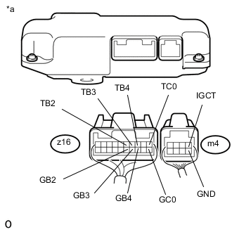
Text in Illustration *a Rear view of wire harness connector
(to Battery Smart Unit)
Measure the resistance according to the value(s) in the table below.
Standard Resistance Tester Connection Switch Condition Standard Resistance z16-5 (TB2) - m4-1 (IGCT) Power switch off 10 kΩ or higher z16-5 (TB2) - m4-5 (GND) Power switch off 10 kΩ or higher z16-15 (GB2) - m4-1 (IGCT) Power switch off 10 kΩ or higher z16-15 (GB2) - m4-5 (GND) Power switch off 10 kΩ or higher z16-4 (TB3) - m4-1 (IGCT) Power switch off 10 kΩ or higher z16-4 (TB3) - m4-5 (GND) Power switch off 10 kΩ or higher z16-14 (GB3) - m4-1 (IGCT) Power switch off 10 kΩ or higher z16-14 (GB3) - m4-5 (GND) Power switch off 10 kΩ or higher z16-3 (TB4) - m4-1 (IGCT) Power switch off 10 kΩ or higher z16-3 (TB4) - m4-5 (GND) Power switch off 10 kΩ or higher z16-13 (GB4) - m4-1 (IGCT) Power switch off 10 kΩ or higher z16-13 (GB4) - m4-5 (GND) Power switch off 10 kΩ or higher -
Measure the resistance according to the value(s) in the table below.
Standard Resistance Tester Connection Switch Condition Standard Resistance z16-1 (TC0) - m4-1 (IGCT) Power switch off 10 kΩ or higher z16-1 (TC0) - m4-5 (GND) Power switch off 10 kΩ or higher z16-11 (GC0) - m4-1 (IGCT) Power switch off 10 kΩ or higher z16-11 (GC0) - m4-5 (GND) Power switch off 10 kΩ or higher -
Connect the battery smart unit connectors.
-
Install the No. 4 hybrid vehicle battery carrier bracket sub-assembly.
OK
REPLACE BATTERY SMART UNIT Click here
NG
-
-
CHECK HARNESS AND CONNECTOR (BATTERY TEMPERATURE SENSOR)
CAUTION:
Be sure to wear insulated gloves and protective goggles.
-
Check that the service plug grip is not installed.
Note
After removing the service plug grip, do not turn the power switch on (READY), unless instructed by the repair manual because this may cause a malfunction.
-
Remove the No. 4 hybrid vehicle battery carrier bracket sub-assembly Click here.
-
Check the wire harness and connectors of the battery temperature sensor for abnormalities by sight and touch.
Specified Condition There are no open or short circuits in the wire harness and connectors. There are no short circuits to other wire harnesses. Tech Tips
Because the battery harness is not available as a supply part, if the harness cannot be repaired, replace the HV battery assembly.
-
Install the No. 4 hybrid vehicle battery carrier bracket sub-assembly.
OK
REPLACE HV BATTERY Click here
NG
REPAIR OR REPLACE HARNESS OR CONNECTOR (BATTERY TEMPERATURE SENSOR)
-