CYLINDER HEAD GASKET INSTALLATION
CAUTION / NOTICE / HINT
Tech Tips
Perform "Inspection After Repair" after replacing the cylinder head sub-assembly.
-
w/ EGR System: Click here
-
w/o EGR System: Click here
PROCEDURE
-
INSPECT VALVE LASH ADJUSTER ASSEMBLY
-
INSPECT NO. 1 VALVE ROCKER ARM SUB-ASSEMBLY
-
INSTALL CYLINDER HEAD GASKET
-
Remove any old packing (FIPG) material and be careful not to drop any oil on the contact surfaces of the cylinder head sub-assembly or cylinder block sub-assembly.
-
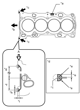
Text in Illustration *1 Cylinder Head Gasket *a Lot No. *b Engine Front Side *c Seal Packing *d View A *e 3.0 to 5.0 mm (0.118 to 0.197 in.) *f 38 mm (1.50 in.) *g 152.5 mm (6.00 in.) *h 7.0 to 9.0 mm (0.276 to 0.354 in.) *i 5.0 to 7.0 mm (0.197 to 0.276 in.) Apply seal packing to a new cylinder head gasket as shown in the illustration.
Seal packing Toyota Genuine Seal Packing Black, Three Bond 1207B or equivalent. Note
-
Be sure to clean and degrease the contact surfaces.
-
Install the cylinder head gasket within 3 minutes and tighten the cylinder head set bolts within 15 minutes after applying seal packing.
-
-
-
INSTALL CYLINDER HEAD SUB-ASSEMBLY
Tech Tips
The cylinder head set bolts are tightened in 4 progressive steps.
-
Place the cylinder head sub-assembly on the cylinder block sub-assembly.
Note
-
Check and clean the cylinder head set bolts and their installation holes.
-
Make sure that no oil is on the mounting surface of the cylinder head sub-assembly.
-
Gently place the cylinder head sub-assembly in order not to damage the cylinder head gasket.
-
-
Apply a light coat of engine oil to the threads and under the heads of the cylinder head set bolts.
-
Install the 10 plate washers to the 10 cylinder head set bolts.
-
Step 1:
-
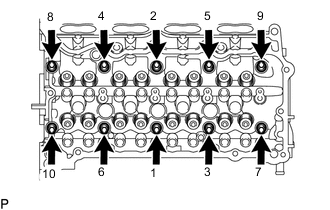
Using a 10 mm bi-hexagon wrench, install and uniformly tighten the 10 cylinder head set bolts in several steps, in the sequence shown in the illustration.
- Torque:
- 36 N*m { 367 kgf*cm, 27 ft.*lbf }
Note
-
Install the cylinder head set bolt to the same place it was removed from.
-
Be careful not to drop the plate washers into the cylinder head sub-assembly.
-
-
Step 2:
-
Tighten the cylinder head set bolts again in the sequence shown in the illustration to make sure that they are tightened to the specified torque.
- Torque:
- 36 N*m { 367 kgf*cm, 27 ft.*lbf }
-
-
Step 3:
-
Mark the front side of each cylinder head set bolt head with paint.
-
Tighten the cylinder head set bolts an additional 90°.
-
-
Step 4:
-
Tighten the cylinder head set bolts an additional 90°.
-
Check that the paint marks are now at a 180° angle to the front.
Note
After installing the cylinder head sub-assembly, wipe off any excess seal packing within 5 minutes.
-
-
-
INSTALL VALVE STEM CAP
-
Apply a light coat of engine oil to the valve stem caps.
-
Install the 16 valve stem caps to the valve stem ends.
Note
-
Install the valve stem cap to the same place it was removed from.
-
Do not drop the valve stem caps into the cylinder head sub-assembly.
-
-
-
INSTALL VALVE LASH ADJUSTER ASSEMBLY
Note
-
Keep the valve lash adjuster assembly free from dirt and foreign objects.
-
Only use clean engine oil.
-
If the valve lash adjuster assembly is tilted after bleeding, oil will leak. Make sure to bleed the valve lash adjuster assembly again.
-
Bleed the valve lash adjuster assembly Click here.
-
If the plunger moves, bleed the valve lash adjuster assembly again.
-
Place the valve lash adjuster assembly into a container full of new engine oil, and then fill the low pressure chamber with engine oil.
-
Apply engine oil to the outer surface of the valve lash adjuster body and the tip of the plunger, and then install the valve lash adjuster assembly while turning it.
Note
Install the valve lash adjuster assembly to the same place it was removed from.
-
-
INSTALL NO. 1 VALVE ROCKER ARM SUB-ASSEMBLY
-
Apply engine oil to the valve lash adjuster assembly tips and valve stem caps.
-
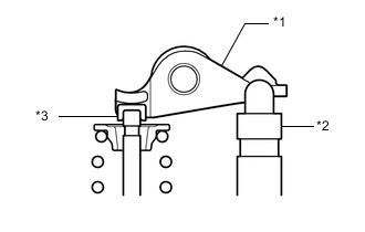
Text in Illustration *1 No. 1 Valve Rocker Arm Sub-assembly *2 Valve Lash Adjuster Assembly *3 Valve Stem Cap Install the 16 No. 1 valve rocker arm sub-assemblies as shown in the illustration.
Note
Install the No. 1 valve rocker arm sub-assembly to the same place it was removed from.
-
-
INSTALL SPARK PLUG
-
CONNECT NO. 9 WATER BY-PASS HOSE
-
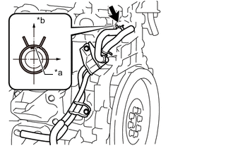
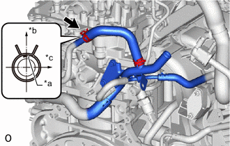
Text in Illustration *a Paint Mark *b Upper Side Connect the No. 9 water by-pass hose to the cylinder head sub-assembly, and slide the clip to secure the hose.
Note
-
Connect the hose clamp so that it is positioned as shown in the illustration.
-
Connect the No. 9 water by-pass hose with the paint mark facing upward.
-
-
-
INSTALL NO. 2 WATER BY-PASS PIPE
-
Install the No. 2 water by-pass pipe to the cylinder head sub-assembly with the 2 bolts.
- Torque:
- 10 N*m { 102 kgf*cm, 7 ft.*lbf }
-
-
INSTALL WATER BY-PASS PIPE (w/o EGR System)
-
Install the water by-pass pipe to the cylinder head sub-assembly with the nut and bolt.
- Torque:
- 21 N*m { 214 kgf*cm, 15 ft.*lbf }
-
-
INSTALL NO. 5 WATER BY-PASS HOSE (w/o EGR System)
-
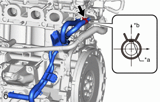
Text in Illustration *a Paint Mark *b Upper Side *c Rear Side Connect the No. 5 water by-pass hose, and slide the clip to secure the hose.
Note
-
Connect the hose clamp so that it is positioned as shown in the illustration.
-
Connect the No. 5 water by-pass hose with the paint mark facing upward.
-
-
-
INSTALL NO. 6 WATER BY-PASS HOSE (w/o EGR System)
-
Text in Illustration *a Paint Mark *b Upper Side Connect the No. 6 water by-pass hose to the water by-pass pipe, and slide the clip to secure the hose.
-
-
INSTALL CAMSHAFT HOUSING SUB-ASSEMBLY
-
INSTALL FUEL INJECTOR SET
-
INSTALL FUEL INJECTOR ASSEMBLY
-
INSTALL ENGINE MOTOR CABLE CLAMP BRACKET (w/o EGR System)
-
REMOVE ENGINE FROM ENGINE STAND (w/o EGR System)
-
INSTALL EXHAUST MANIFOLD CONVERTER SUB-ASSEMBLY
-
INSTALL EGR COOLER ASSEMBLY (w/ EGR System)