CYLINDER HEAD GASKET REMOVAL
PROCEDURE
-
REMOVE EGR COOLER ASSEMBLY (w/ EGR System)
-
REMOVE EXHAUST MANIFOLD CONVERTER SUB-ASSEMBLY
-
INSTALL ENGINE TO ENGINE STAND (w/o EGR System)
-
REMOVE ENGINE MOTOR CABLE CLAMP BRACKET (w/o EGR System)
-
REMOVE FUEL INJECTOR ASSEMBLY
-
REMOVE FUEL INJECTOR SET
-
REMOVE CAMSHAFT HOUSING SUB-ASSEMBLY
-
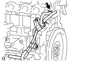
REMOVE NO. 6 WATER BY-PASS HOSE (w/o EGR System)
-
Slide the clip and disconnect the No. 6 water by-pass hose from the water by-pass pipe.
-
-
REMOVE NO. 5 WATER BY-PASS HOSE (w/o EGR System)
-
Slide the clip and disconnect the No. 5 water by-pass hose from the water by-pass pipe.
-
-
REMOVE WATER BY-PASS PIPE (w/o EGR System)
-
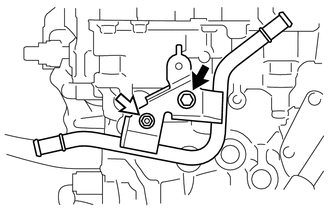
Remove the nut, bolt and water by-pass pipe from the cylinder head sub-assembly.
Text in Illustration 
Bolt 
Nut
-
-
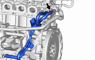
REMOVE NO. 9 WATER BY-PASS HOSE
-
Slide the clip and disconnect the No. 9 water by-pass hose from the cylinder head sub-assembly.
-
-
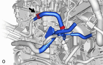
REMOVE NO. 2 WATER BY-PASS PIPE
-
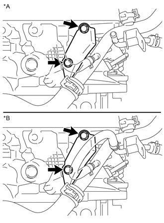
Text in Illustration *A w/ EGR System *B w/o EGR System Remove the 2 bolts and disconnect the No. 2 water by-pass pipe.
-
-
REMOVE SPARK PLUG
-
REMOVE NO. 1 VALVE ROCKER ARM SUB-ASSEMBLY
-
Remove the 16 No. 1 valve rocker arm sub-assemblies from the cylinder head sub-assembly.
Tech Tips
Be sure to keep the removed parts for each installation position separate.
-
-
REMOVE VALVE LASH ADJUSTER ASSEMBLY
-
Remove the 16 valve lash adjuster assemblies from the cylinder head sub-assembly.
Tech Tips
Be sure to keep the removed parts for each installation position separate.
-
-
REMOVE VALVE STEM CAP
-
Remove the 16 valve stem caps from the valve stem ends.
Tech Tips
Be sure to keep the removed parts for each installation position separate.
-
-
REMOVE CYLINDER HEAD SUB-ASSEMBLY
-
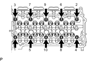
Using a 10 mm bi-hexagon wrench, uniformly loosen the 10 cylinder head set bolts in the sequence shown in the illustration. Remove the 10 cylinder head set bolts and plate washers.
Note
-
Be careful not to drop the plate washers into the cylinder head sub-assembly.
-
Cylinder head sub-assembly warpage or cracking could result from removing cylinder head set bolts in an incorrect order.
Tech Tips
Be sure to keep the removed parts for each installation position separate.
-
-
Remove the cylinder head sub-assembly.
-
-
REMOVE CYLINDER HEAD GASKET
-
Remove the cylinder head gasket from the cylinder block sub-assembly.
-
-
INSPECT CYLINDER HEAD SET BOLT
-
INSPECT CYLINDER HEAD SUB-ASSEMBLY