HYBRID CONTROL SYSTEM, Diagnostic DTC:P0AA1-233
| DTC Code | DTC Name |
|---|---|
| P0AA1-233 | Hybrid Battery Positive Contactor Circuit Stuck Closed |
DESCRIPTION
-
Refer to the description for DTC P0AE6-225 Click here.
-
This circuit uses the power management control ECU to monitor the system main relays and stops the system if a malfunction is detected in the relays, because it may be impossible to shut off the high-voltage system if any of the relays becomes stuck.
| DTC No. | INF Code | DTC Detection Condition | Trouble Area |
|---|---|---|---|
| P0AA1 | 233 | SMRP, SMRB and SMRG on the HV battery positive and negative sides are stuck closed. |
|
WIRING DIAGRAM
Refer to the wiring diagram for DTC P0AE6-225 Click here.
CAUTION / NOTICE / HINT
CAUTION:
-
When performing P0AA1-233 troubleshooting, use either a tool wrapped with vinyl insulation tape or an insulated tool. It is extremely dangerous when a high-voltage charge passes through a non-insulated tool causing a short.
-
Before inspecting the high-voltage system or disconnecting the low voltage connector of the inverter with converter assembly, take safety precautions such as wearing insulated gloves and removing the service plug grip to prevent electrical shocks. After removing the service plug grip, put it in your pocket to prevent other technicians from accidentally reconnecting it while you are working on the high-voltage system.
-
After removing the service plug grip, wait for at least 10 minutes before touching any of the high-voltage connectors or terminals. After waiting for 10 minutes, check the voltage at the terminals in the inspection point in the inverter with converter assembly. The voltage should be 0 V before beginning work Click here.
Tech Tips
Waiting for at least 10 minutes is required to discharge the high-voltage capacitor inside the inverter with converter assembly.
Note
-
After turning the power switch off, waiting time may be required before disconnecting the cable from the negative (-) auxiliary battery terminal. Therefore, make sure to read the disconnecting the cable from the negative (-) auxiliary battery terminal notices before proceeding with work Click here.
-
If the DTCs are cleared or the cable is disconnected and reconnected to the negative (-) auxiliary battery terminal before performing repairs, turning the power switch on (READY) may cause a malfunction. Do not turn the power switch on (READY).
-
Do not turn the power switch on (IG) with the service plug grip removed, as this may cause a malfunction.
-
If DTC P0AA1-233 is output, do not install the service plug grip before completing repair.
If the service plug grip is not removed, the HV battery will gradually discharge and the SOC will decrease.
Tech Tips
If P0AA1-233 is stored, the hybrid system cannot be turned on.
PROCEDURE
-
CHECK DTC OUTPUT (HYBRID CONTROL)
-
Connect the GTS to the DLC3.
-
Turn the power switch on (IG).
-
Enter the following menus: Powertrain / Hybrid Control / Trouble Codes.
-
Check if DTCs are output.
Result Result Proceed to P0AA1-233 only is output. A Any of the following DTCs are also output. B DTC No. Relevant Diagnosis P06B0-163 Sensor Power Supply "A" Circuit/Open P06D6-511 Sensor Reference Voltage "F" Circuit/Open P06E6-164 Sensor Power Supply "C" Circuit/Open P0A1A-151, 658, 791 Generator Control Module P0A1B-786, 794 Drive Motor "A" Control Module P0A1D-148 Hybrid Powertrain Control Module P0A3F-243 Drive Motor "A" Position Sensor Circuit P0A40-500 Drive Motor "A" Position Sensor Circuit Range/Performance P0A41-245 Drive Motor "A" Position Sensor Circuit Low P0A4B-253 Generator Position Sensor Circuit P0A4C-513 Generator Position Sensor Circuit Range/Performance P0A4D-255 Generator Position Sensor Circuit Low P0ADC-226 Hybrid Battery Positive Contactor Control Circuit High P0AE0-228 Hybrid Battery Negative Contactor Control Circuit High P0AE7-224 Hybrid Battery Precharge Contactor Control Circuit High P0C76-523 Hybrid Battery System Discharge Time Too Long P0CA3-442 DC/DC Converter Step Up Voltage Performance P0D2E-586 Drive Motor "A" Inverter Voltage Sensor Circuit Range/Performance P0D2F-266 Drive Motor "A" Inverter Voltage Sensor Circuit Low P0D30-267 Drive Motor "A" Inverter Voltage Sensor Circuit High P1C2A-155 Generator A/D Converter Circuit P1C73-512 Sensor Standard Voltage "F" Circuit/Open P1CA6-156 Generator Control Module Malfunction P1CA7-193 Drive Motor Control Module Malfunction P1CAC-200 Generator Position Sensor Angle Malfunction P1CAD-168 Drive Motor "A" Position Sensor Angle Malfunction P1CAF-792 Generator Position Sensor REF Signal Cycle Malfunction P1CB0-795 Drive Motor "A" Position Sensor REF Signal Cycle Malfunction P1CB2-793 Generator Position Sensor REF Signal Stop Malfunction P1CB3-796 Drive Motor "A" Position Sensor REF Signal Stop Malfunction P2511-149 ECM/PCM Power Relay Sensor Circuit Intermittent P3004-132 Power Cable Malfunction P3133-659 Communication Error from Generator to Drive Motor "A" P3134-661 Communication Error from Drive Motor "A" to Generator P324E-788 MG-ECU Power Relay Intermittent Circuit U0110 (all INF codes)*1 Lost Communication with Drive Motor Control Module Tech Tips
-
*1: If any INF codes are output for this DTC, refer to the corresponding diagnostic procedure.
-
P0AA1-233 may be output due to a malfunction which causes the DTCs in the table above to be output. In this case, first troubleshoot the output DTCs in the table above. Then, perform a reproduction test to check that no DTCs are output.
-
-
Turn the power switch off.
B 
GO TO DTC CHART (HYBRID CONTROL SYSTEM) Click here
A 
-
-
CHECK FREEZE FRAME DATA (HYBRID CONTROL)
-
Connect the GTS to the DLC3.
-
Turn the power switch on (IG).
-
Enter the following menus: Powertrain / Hybrid Control / Trouble Codes.
-
Read the freeze frame data of DTC P0AA1-233.
Result Result Proceed to VH-Voltage after Boosting minus VL-Voltage before Boosting is 100 V or less. A The preceding condition is not satisfied. B -
Turn the power switch off.
B
REPLACE INVERTER WITH CONVERTER ASSEMBLY Click here
A
-
-
CHECK CONNECTOR CONNECTION CONDITION (POWER MANAGEMENT CONTROL ECU CONNECTOR)
-
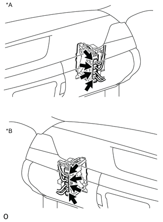
Text in Illustration *A for LHD *B for RHD Check the connector connections and contact pressure of the relevant terminals for the power management control ECU connectors Click here.
OK The connectors are connected securely and there are no contact pressure problems.
OK 
CHECK CONNECTOR CONNECTION CONDITION (FLOOR WIRE CONNECTOR) Click here
NG
-
-
CONNECT SECURELY
NEXT
-
CHECK CONNECTOR CONNECTION CONDITION (FLOOR WIRE CONNECTOR)
-
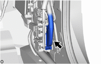
Check the connector connections and contact pressure of the relevant terminals for the floor wire connector Click here.
OK The connectors are connected securely and there are no contact pressure problems.
OK
CHECK CONNECTOR CONNECTION CONDITION (NO. 2 HV BATTERY PACK WIRE CONNECTOR) Click here
NG
-
-
CONNECT SECURELY
NEXT
-
CHECK CONNECTOR CONNECTION CONDITION (NO. 2 HV BATTERY PACK WIRE CONNECTOR)
CAUTION:
Be sure to wear insulated gloves.
-
Check that the service plug grip is not installed.
Note
After removing the service plug grip, do not turn the power switch on (READY), unless instructed by the repair manual because this may cause a malfunction.
-
Remove the front luggage compartment trim cover Click here.
-
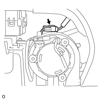
Check the connection condition of the No. 2 HV battery pack wire connector and the contact pressure of each terminal. Check the terminals for deformation, and check the connector for water ingress and foreign matter Click here.
-
The connector is connected securely.
-
The terminals are not deformed and are connected securely.
-
No water or foreign matter in the connector.
OK:
Result Result Proceed to OK A NG (The connector is not connected securely.) B NG (The terminals are not making secure contact or are deformed, or water or foreign matter exists in the connector.) C -
-
Install the front luggage compartment trim cover.
A
CHECK CONNECTOR CONNECTION CONDITION (HYBRID BATTERY JUNCTION BLOCK ASSEMBLY CONNECTOR) Click here
C
REPAIR OR REPLACE HARNESS OR CONNECTOR Click here
B
-
-
CONNECT SECURELY
NEXT
CHECK CONNECTOR CONNECTION CONDITION (HYBRID BATTERY JUNCTION BLOCK ASSEMBLY CONNECTOR) Click here
-
REPAIR OR REPLACE HARNESS OR CONNECTOR
NEXT
-
CHECK CONNECTOR CONNECTION CONDITION (HYBRID BATTERY JUNCTION BLOCK ASSEMBLY CONNECTOR)
CAUTION:
Be sure to wear insulated gloves.
-
Check that the service plug grip is not installed.
Note
After removing the service plug grip, do not turn the power switch on (IG), unless instructed by the repair manual because this may cause a malfunction.
-
Remove the No. 2 hybrid vehicle battery shield reinforcement Click here.
-
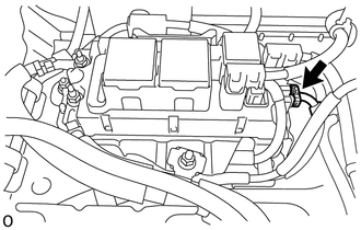
Check the connector connections and contact pressure of the relevant terminals for the hybrid battery junction block assembly connector Click here.
OK The connectors are connected securely and there are no contact pressure problems. -
Install the No. 2 hybrid vehicle battery shield reinforcement.
OK
CHECK GROUND WIRE CONNECTION CONDITION (SMR ACTIVATION LOW-VOLTAGE CIRCUIT) Click here
NG
-
-
CONNECT SECURELY
NEXT
-
CHECK GROUND WIRE CONNECTION CONDITION (SMR ACTIVATION LOW-VOLTAGE CIRCUIT)
-
Check the installation condition of the ground wire T4.
OK The ground wire T4 is securely installed.
OK
CHECK HARNESS AND CONNECTOR (POWER MANAGEMENT CONTROL ECU - HYBRID BATTERY JUNCTION BLOCK ASSEMBLY) Click here
NG
-
-
CONNECT SECURELY
NEXT
-
CHECK HARNESS AND CONNECTOR (POWER MANAGEMENT CONTROL ECU - HYBRID BATTERY JUNCTION BLOCK ASSEMBLY)
CAUTION:
Be sure to wear insulated gloves.
-
Check that the service plug grip is not installed.
Note
After removing the service plug grip, do not turn the power switch on (IG), unless instructed by the repair manual because this may cause a malfunction.
-
Remove the front luggage compartment trim cover Click here.
-
Disconnect the connector from the hybrid battery junction block assembly.
-
Disconnect the connector from the power management control ECU.
-
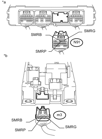
Text in Illustration *a Rear view of wire harness connector
(to Power Management Control ECU)
*b Rear view of wire harness connector
(to Hybrid Battery Junction Block Assembly)
Measure the resistance according to the value(s) in the table below.
Standard Resistance Check for Open Tester Connection Switch Condition Specified Condition N91-4 (SMRB) - m3-4 (SMRB) Power switch off Below 1 Ω N91-2 (SMRG) - m3-1 (SMRG) Power switch off Below 1 Ω N91-3 (SMRP) - m3-3 (SMRP) Power switch off Below 1 Ω Check for Short Tester Connection Switch Condition Specified Condition N91-4 (SMRB) and m3-4 (SMRB) - Body ground and other terminals Power switch off 10 kΩ or higher N91-2 (SMRG) and m3-1 (SMRG) - Body ground and other terminals Power switch off 10 kΩ or higher N91-3 (SMRP) and m3-3 (SMRP) - Body ground and other terminals Power switch off 10 kΩ or higher -
Connect the power management control ECU connector.
-
Connect the hybrid battery junction block assembly connector.
-
Install the front luggage compartment trim cover.
OK
CHECK HARNESS AND CONNECTOR (HYBRID BATTERY JUNCTION BLOCK ASSEMBLY - BODY GROUND) Click here
NG
-
-
REPAIR OR REPLACE HARNESS OR CONNECTOR
NEXT
-
CHECK HARNESS AND CONNECTOR (HYBRID BATTERY JUNCTION BLOCK ASSEMBLY - BODY GROUND)
CAUTION:
Be sure to wear insulated gloves.
-
Check that the service plug grip is not installed.
Note
After removing the service plug grip, do not turn the power switch on (READY), unless instructed by the repair manual because this may cause a malfunction.
-
Remove the upper hybrid battery cover sub-assembly Click here.
-
Disconnect the connector from the hybrid battery junction block assembly.
-
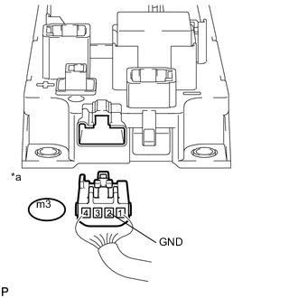
Text in Illustration *a Rear view of wire harness connector
(to Hybrid Battery Junction Block Assembly)
Measure the resistance according to the value(s) in the table below.
Standard Resistance Tester Connection Switch Condition Specified Condition m3-2 (GND) - Body ground Power switch off Below 1 Ω -
Connect the hybrid battery junction block assembly connector.
-
Install the upper hybrid battery cover sub-assembly.
OK
INSPECT HYBRID BATTERY JUNCTION BLOCK ASSEMBLY (SMRB, SMRG, SMRP) Click here
NG
-
-
REPAIR OR REPLACE HARNESS OR CONNECTOR
NEXT
-
INSPECT HYBRID BATTERY JUNCTION BLOCK ASSEMBLY (SMRB, SMRG, SMRP)
CAUTION:
Be sure to wear insulated gloves.
-
Check that the service plug grip is not installed.
Note
After removing the service plug grip, do not turn the power switch on (IG), unless instructed by the repair manual because this may cause a malfunction.
-
Remove the upper hybrid battery cover sub-assembly Click here.
-
Disconnect the hybrid battery junction block assembly connector.
-
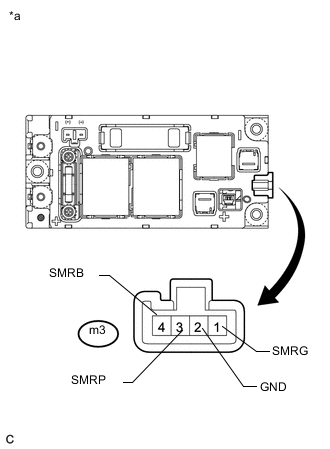
Text in Illustration *a Component without harness connected
(Hybrid Battery Junction Block Assembly)
Measure the resistance according to the value(s) in the table below.
Standard Resistance Tester Connection Condition Specified Condition m3-4 (SMRB) - m3-2 (GND) -40 to 80°C (-40 to 176°F) 18.4 to 36.3 Ω m3-1 (SMRG) - m3-2 (GND) -40 to 80°C (-40 to 176°F) 18.4 to 36.3 Ω m3-3 (SMRP) - m3-2 (GND) -40 to 80°C (-40 to 176°F) 112 to 274 Ω -
Reconnect the hybrid battery junction block assembly connector.
-
Install the hybrid battery junction block assembly.
NG
REPLACE HYBRID BATTERY JUNCTION BLOCK ASSEMBLY Click here
OK
-
-
CHECK HYBRID BATTERY JUNCTION BLOCK ASSEMBLY (SMRB, SMRG, SMRP)
CAUTION:
Be sure to wear insulated gloves.
-
Check that the service plug grip is not installed.
Note
After removing the service plug grip, do not turn the power switch on (IG), unless instructed by the repair manual because this may cause a malfunction.
-
Remove the upper hybrid battery cover sub-assembly Click here.
-
Disconnect the 2 high voltage cable connectors of the HV battery from the hybrid battery junction block assembly.
-
Disconnect the No. 2 frame wire from the hybrid battery junction block assembly.
-
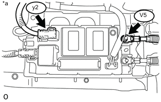
Text in Illustration *a Component without harness connected
(Hybrid Battery Junction Block Assembly)
Measure the resistance according to the value(s) in the table below.
Standard Resistance (SMRB) Tester Connection Switch Condition Specified Condition V5-1 (CBI) - y2-1 (+) Power switch off 10 kΩ or higher Tech Tips
-
If a system main relay is stuck closed, inspect the hybrid battery junction block assembly without removing it from the vehicle, in order to keep the relay closed.
-
If the result of reading the freeze frame data is A, the hybrid battery junction block assembly must be replaced. Measuring resistance can determine that this is either a present or past malfunction.
-
-
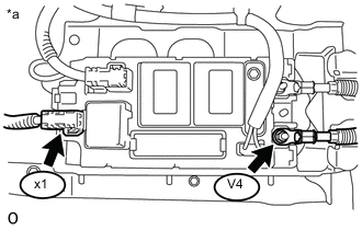
Text in Illustration *a Component without harness connected
(Hybrid Battery Junction Block Assembly)
Measure the resistance according to the value(s) in the table below.
Standard Resistance (SMRG, SMRP) Tester Connection Switch Condition Specified Condition V4-1 (CEI) - x1-1 (-) Power switch off 10 kΩ or higher Tech Tips
-
If a system main relay is stuck closed, inspect the hybrid battery junction block assembly without removing it from the vehicle, in order to keep the relay closed.
-
If the result of reading the freeze frame data is A, the hybrid battery junction block assembly must be replaced. Measuring resistance can determine that this is either a present or past malfunction.
-
If the resistance is between 28.5 and 31.5 Ω, it can be determined that SMRP is stuck closed.
-
-
Reconnect the 2 high voltage cable connectors of the HV battery.
-
Reconnect the No. 2 frame wire to the hybrid battery junction block assembly.
-
Install the upper hybrid battery cover sub-assembly.
NG
REPLACE HYBRID BATTERY JUNCTION BLOCK ASSEMBLY Click here
OK
-
-
REPLACE HYBRID BATTERY JUNCTION BLOCK ASSEMBLY
NEXT
CHECK POWER MANAGEMENT CONTROL ECU (CHECK FOR NORMAL OPERATION) Click here
-
REPLACE HYBRID BATTERY JUNCTION BLOCK ASSEMBLY
NEXT
CHECK POWER MANAGEMENT CONTROL ECU (CHECK FOR NORMAL OPERATION) Click here
-
REPLACE HYBRID BATTERY JUNCTION BLOCK ASSEMBLY
NEXT
-
CHECK POWER MANAGEMENT CONTROL ECU (CHECK FOR NORMAL OPERATION)
-
Install the service plug grip.
-
Turn the power switch on (IG).
-
Clear the DTCs Click here.
-
Turn the power switch off and wait for 30 seconds or more.
-
Turn the power switch on (READY).
-
Enter the following menus: Powertrain / Hybrid Control / Data List / Power Resource VB, VL-Voltage before Boosting.
-
According to the display on the GTS, read the Data List and monitor the values of "Power Resource VB" and "VL-Voltage before Boosting" for 3 minutes.
Result Result Proceed to Difference between "Power Resource VB" and "VL-Voltage before Boosting" is always less than 100 V. A Difference between "Power Resource VB" and "VL-Voltage before Boosting" is 100 V or more. B -
Turn the power switch off.
A
END
B
REPLACE POWER MANAGEMENT CONTROL ECU AND HYBRID BATTERY JUNCTION BLOCK ASSEMBLY
-