HYBRID CONTROL SYSTEM, Diagnostic DTC:P0C2C-888, P0C2C-889
| DTC Code | DTC Name |
|---|---|
| P0C2C-888 | Auxiliary Transmission Fluid Pump Control Module Feedback Signal Range / Performance |
| P0C2C-889 | Auxiliary Transmission Fluid Pump Control Module Feedback Signal Range / Performance |
DESCRIPTION
Refer to the description for DTC P0C29-865 Click here.
| DTC No. | INF Code | DTC Detection Condition | Trouble Area |
|---|---|---|---|
| P0C2C | 888 | The power management control ECU receives signals that indicate a malfunction (TPST cycle error or noise) in the oil pump motor controller. | Oil pump motor controller |
| P0C2C | 889 | The power management control ECU receives signals that indicate a malfunction (TPST duty error) in the oil pump motor controller. |
WIRING DIAGRAM
Refer to the wiring diagram for DTC P0867-882 Click here.
PROCEDURE
-
CHECK POWER MANAGEMENT CONTROL ECU (CHECK WAVEFORM)
-
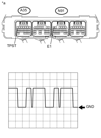
Text in Illustration *a Rear view of wire harness connector
(to Power Management Control ECU)
Connect an oscilloscope to the power management control ECU terminals specified in the table below, and measure the waveform.
Item Contents Terminal A35-17 (TPST) - N91-6 (E1) Equipment Setting 5 V/DIV., 5 ms./DIV. Condition Power switch on (IG) Result Result Proceed to There are no interruptions or distortions in the waveform. (Amount of noise is small.) A There is an interruption or distortion in the waveform. (Amount of noise is large.) B -
Turn the power switch off.
B 
ELIMINATE CAUSE OF NOISE
A 
-
-
CHECK CONNECTOR CONNECTION CONDITION (OIL PUMP MOTOR CONTROLLER CONNECTOR)
Note
Before disconnecting the connectors, confirm that they are properly connected by checking that the locking claws are engaged and that the connectors cannot be pulled out.
-
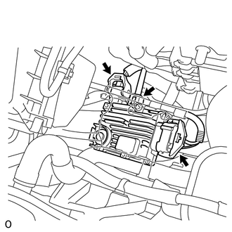
Check the connections of the oil pump motor controller connectors Click here.
OK The connectors are connected securely and there are no contact problems. Tech Tips
For connector A, when connecting it, insert it with the locking lever in the raised position. Rotate the lever downward and make sure that the connector is pulled into its socket. When the locking lever is in its fully closed position, a click will be heard as its locking claws engage. After the click is heard, pull up on the connector to confirm that it is properly connected.
NG
CONNECT SECURELY
OK
-
-
CHECK CONNECTOR CONNECTION CONDITION (POWER MANAGEMENT CONTROL ECU CONNECTOR)
-
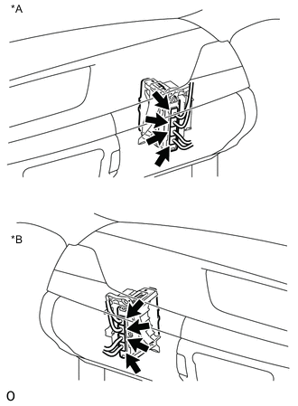
Text in Illustration *A for LHD *B for RHD Check the connector connections and contact pressure of the relevant terminals for the power management control ECU connectors Click here.
OK The connectors are connected securely and there are no contact pressure problems.
OK
REPLACE OIL PUMP MOTOR CONTROLLER Click here
NG
CONNECT SECURELY
-