HYBRID CONTROL SYSTEM, Diagnostic DTC:P0868-866, P0868-894
| DTC Code | DTC Name |
|---|---|
| P0868-866 | Transmission Fluid Pressure Low |
| P0868-894 | Transmission Fluid Pressure Low |
DESCRIPTION
Refer to the description for DTC P0731-871 Click here.
| DTC No. | INF Code | DTC Detection Condition | Trouble Area |
|---|---|---|---|
| P0868 | 866 | Difference between the value of SP2 rotation speed multiplied by the gear ratio of the 2-stage motor speed reduction planetary gear unit and the MG2 rotation speed exceeds a specified value continuously for a specified time (at a vehicle speed of 24 mph (39 km/h) or more). |
|
| 894 | Difference between the value of SP2 rotation speed multiplied by the gear ratio of the 2-stage motor speed reduction planetary gear unit and the MG2 rotation speed exceeds a specified value continuously for a specified time (at a vehicle speed below 24 mph (39 km/h)). |
WIRING DIAGRAM
Refer to the wiring diagram for DTC P0722-854 Click here.
Refer to the wiring diagram for DTC P0731-871 Click here.
Refer to the wiring diagram for DTC P0867-882 Click here.
Refer to the wiring diagram for DTC P1CAC-200 Click here.
CAUTION / NOTICE / HINT
Tech Tips
Slightly shake the wire harness and connector vertically and horizontally, and check that the malfunction does not occur Click here.
PROCEDURE
-
CHECK DTC OUTPUT (HYBRID CONTROL)
-
Connect the GTS to the DLC3.
-
Turn the power switch on (IG).
-
Enter the following menus: Powertrain / Hybrid Control / Trouble Codes.
-
Read the DTCs and Freeze Frame Data, and then compare the Freeze Frame Data values of "Motor(MG2) Revolution" and "Motor(MG2) Revolution by Rotation Angle Sensor" for each time series.
Tech Tips
The "Freeze Frame Data Example" below is only one example of a malfunction condition and a determination should not be made based on this alone.
Freeze Frame Data Example Item Time Series Unit -3 -2 -1 Detection Point 1 (A) (B) (C) (D) (E) Motor(MG2) Revolution 4000 4000 4000 4000 4000 rpm Motor(MG2) Revolution by Rotation Angle Sensor 4000 4000 0 4000 8000 rpm
-
Time series (A): 4000 rpm - 4000 rpm = 0 rpm
-
Time series (B): 4000 rpm - 4000 rpm = 0 rpm
-
Time series (C): 4000 rpm - 0 rpm = 4000 rpm
-
Time series (D): 4000 rpm - 4000 rpm = 0 rpm
-
Time series (E): 4000 rpm - 8000 rpm = -4000 rpm
-
When normal, "Motor(MG2) Revolution" and "Motor(MG2) Revolution by Rotation Angle Sensor" display approximately the same values.
Result Result Proceed to P0868-866 or P0868-894 only is output. Result of "Motor(MG2) Revolution" - "Motor(MG2) Revolution by Rotation Angle Sensor" is larger than 2000 rpm or below -2000 rpm for 1 or more time series A Other than above B Any of the following DTCs are also output. C DTC No. Relevant Diagnosis P0722-854 Output Speed Sensor Circuit No Signal P0731-873 Gear 1 Incorrect Ratio P0732-869 Gear 2 Incorrect Ratio P0748-850 Pressure Control Solenoid "A" Electrical (Shift Solenoid Valve (SL1)) P0778-851 Pressure Control Solenoid "B" Electrical (Shift Solenoid Valve (SL2)) P0867-880 Transmission Fluid Pressure P0A3F-243 Drive Motor "A" Position Sensor Circuit P0A40-500 Drive Motor "A" Position Sensor Circuit Range / Performance P0A41-245 Drive Motor "A" Position Sensor Circuit Low -
-
Turn the power switch off.
B 
CHECK CONNECTOR CONNECTION CONDITION (POWER MANAGEMENT CONTROL ECU CONNECTOR) Click here
C 
GO TO DTC CHART (HYBRID CONTROL SYSTEM) Click here
A 
-
-
CHECK CONNECTOR CONNECTION CONDITION (INVERTER WITH CONVERTER ASSEMBLY CONNECTOR)
CAUTION:
Be sure to wear insulated gloves.
-
Check that the service plug grip is not installed.
Note
After removing the service plug grip, do not turn the power switch on (READY), unless instructed by the repair manual because this may cause a malfunction.
-
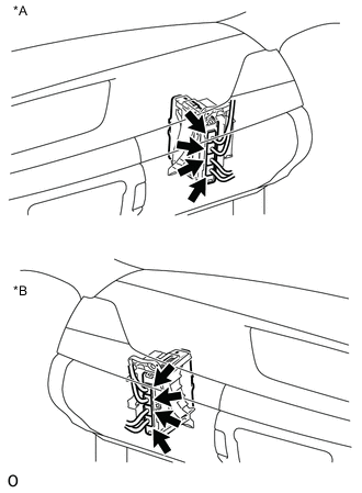
Check the connector connections and contact pressure of the low voltage connectors of the inverter with converter assembly Click here.
Note
Before disconnecting the connector, confirm that it is properly connected by checking that the locking claws are engaged and that the connector cannot be pulled out.
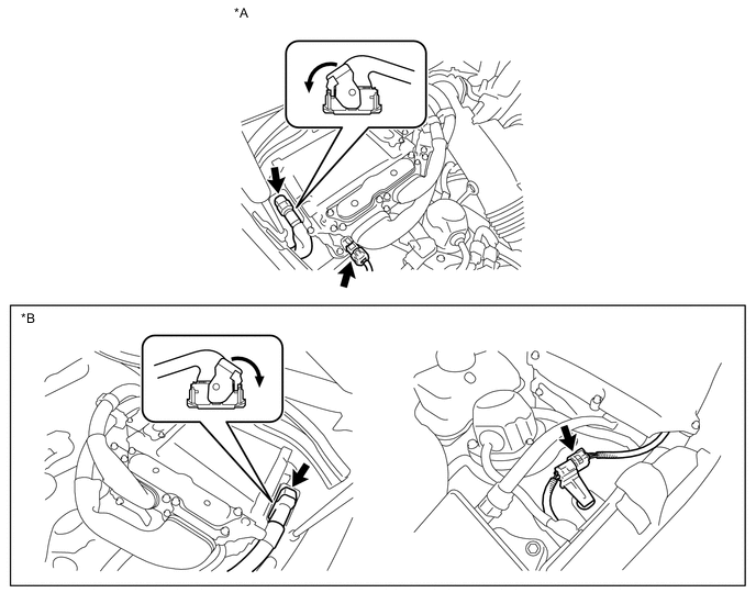
Text in Illustration *A for LHD *B for RHD OK The connectors are connected securely and there are no contact pressure problems. Tech Tips
When connecting the connector, insert it with the locking lever in the raised position. Rotate the lever downward and make sure that the connector is pulled into its socket. When the locking lever is in its fully closed position, a click will be heard as its locking claws engage. After the click is heard, pull up on the connector to confirm that it is properly connected.
NG
CONNECT SECURELY
OK
-
-
CHECK CONNECTOR CONNECTION CONDITION (JUNCTION CONNECTOR)
-
Check the connection of the junction connector Click here.
OK The connector is connected securely and there are no contact problems. 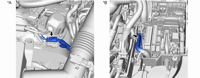
Text in Illustration *A for LHD *B for RHD
NG
CONNECT SECURELY
OK
-
-
CHECK CONNECTOR CONNECTION CONDITION (MOTOR RESOLVER CONNECTOR)
-
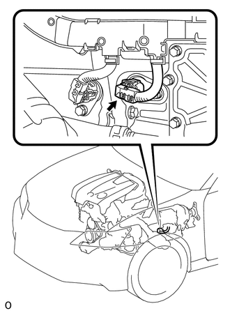
Check the connection condition of the motor resolver connector and the contact pressure of each terminal. Check the terminals for deformation, and check the connector for water ingress and foreign matter Click here.
OK The connector is connected securely and there are no contact problems. Note
If the terminals connect poorly, are damaged, or contain water or foreign matter, repair or replace the wire harness or connector.
NG
CONNECT SECURELY
OK
-
-
CHECK HARNESS AND CONNECTOR (INVERTER WITH CONVERTER ASSEMBLY - MOTOR RESOLVER)
CAUTION:
Be sure to wear insulated gloves.
-
Check that the service plug grip is not installed.
Note
After removing the service plug grip, do not turn the power switch on (READY), unless instructed by the repair manual because this may cause a malfunction.
-
Disconnect the connector from the inverter with converter assembly.
-
Connect the cable to the negative (-) auxiliary battery terminal.
-
Turn the power switch on (IG).
-
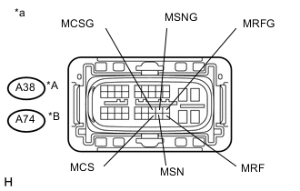
Text in Illustration *A for LHD *B for RHD *a Front view of wire harness connector
(to Inverter with Converter Assembly)
Measure the voltage according to the value(s) in the table below.
Standard Voltage for LHD Tester Connection Switch Condition Specified Condition A38-40 (MRF) - Body ground Power switch on (IG) Below 1 V A38-29 (MRFG) - Body ground Power switch on (IG) Below 1 V A38-39 (MSN) - Body ground Power switch on (IG) Below 1 V A38-28 (MSNG) - Body ground Power switch on (IG) Below 1 V A38-38 (MCS) - Body ground Power switch on (IG) Below 1 V A38-27 (MCSG) - Body ground Power switch on (IG) Below 1 V for RHD Tester Connection Switch Condition Specified Condition A74-40 (MRF) - Body ground Power switch on (IG) Below 1 V A74-29 (MRFG) - Body ground Power switch on (IG) Below 1 V A74-39 (MSN) - Body ground Power switch on (IG) Below 1 V A74-28 (MSNG) - Body ground Power switch on (IG) Below 1 V A74-38 (MCS) - Body ground Power switch on (IG) Below 1 V A74-27 (MCSG) - Body ground Power switch on (IG) Below 1 V Note
Turning the power switch on (IG) with the low voltage connector of the inverter with converter assembly disconnected causes other DTCs to be stored. Clear the DTCs after performing this inspection.
Tech Tips
Slightly shake the wire harness and connector vertically and horizontally, and check that the malfunction does not occur Click here.
-
Turn the power switch off.
-
Disconnect the cable from the negative (-) auxiliary battery terminal.
-
Connect the inverter with converter assembly connector.
NG
REPAIR OR REPLACE HARNESS OR CONNECTOR
OK
-
-
CHECK MOTOR RESOLVER
CAUTION:
Be sure to wear insulated gloves.
-
Check that the service plug grip is not installed.
Note
After removing the service plug grip, do not turn the power switch on (READY), unless instructed by the repair manual because this may cause a malfunction.
-
Disconnect the connector from the inverter with converter assembly.
-
Text in Illustration *A for LHD *B for RHD *a Front view of wire harness connector
(to Inverter with Converter Assembly)
Measure the resistance according to the value(s) in the table below.
Standard Resistance (Check for Open) for LHD Tester Connection Switch Condition Specified Condition A38-40 (MRF) - A38-29 (MRFG) Power switch off 6.0 to 12.0 Ω A38-39 (MSN) - A38-28 (MSNG) Power switch off 12.5 to 24.5 Ω A38-38 (MCS) - A38-27 (MCSG) Power switch off 12.5 to 24.5 Ω for RHD Tester Connection Switch Condition Specified Condition A74-40 (MRF) - A74-29 (MRFG) Power switch off 6.0 to 12.0 Ω A74-39 (MSN) - A74-28 (MSNG) Power switch off 12.5 to 24.5 Ω A74-38 (MCS) - A74-27 (MCSG) Power switch off 12.5 to 24.5 Ω Standard Resistance (Check for Short) for LHD Tester Connection Switch Condition Specified Condition A38-40 (MRF) or A38-29 (MRFG) - Body ground and other terminals Power switch off 10 kΩ or higher A38-39 (MSN) or A38-28 (MSNG) - Body ground and other terminals Power switch off 10 kΩ or higher A38-38 (MCS) or A38-27 (MCSG) - Body ground and other terminals Power switch off 10 kΩ or higher for RHD Tester Connection Switch Condition Specified Condition A74-40 (MRF) or A74-29 (MRFG) - Body ground and other terminals Power switch off 10 kΩ or higher A74-39 (MSN) or A74-28 (MSNG) - Body ground and other terminals Power switch off 10 kΩ or higher A74-38 (MCS) or A74-27 (MCSG) - Body ground and other terminals Power switch off 10 kΩ or higher Tech Tips
Slightly shake the wire harness and connector vertically and horizontally, and check that the malfunction does not occur Click here.
-
Connect the inverter with converter assembly connector.
OK
REPLACE INVERTER WITH CONVERTER ASSEMBLY Click here
NG
-
-
CHECK HARNESS AND CONNECTOR (INVERTER WITH CONVERTER ASSEMBLY - MOTOR RESOLVER)
CAUTION:
Be sure to wear insulated gloves.
-
Check that the service plug grip is not installed.
Note
After removing the service plug grip, do not turn the power switch on (READY), unless instructed by the repair manual because this may cause a malfunction.
-
Disconnect the connector from the inverter with converter assembly.
-
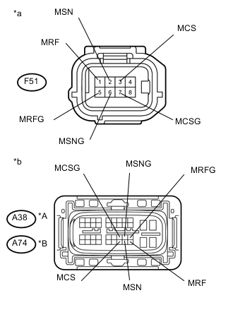
Text in Illustration *A for LHD *B for RHD *a Front view of wire harness connector
(to Motor Resolver)
*b Front view of wire harness connector
(to Inverter with Converter Assembly)
Disconnect the motor resolver connector.
-
Measure the resistance according to the value(s) in the table below.
Standard Resistance (Check for Open) for LHD Tester Connection Switch Condition Specified Condition F51-1 (MRF) - A38-40 (MRF) Power switch off Below 1 Ω F51-5 (MRFG) - A38-29 (MRFG) Power switch off Below 1 Ω F51-2 (MSN) - A38-39 (MSN) Power switch off Below 1 Ω F51-6 (MSNG) - A38-28 (MSNG) Power switch off Below 1 Ω F51-3 (MCS) - A38-38 (MCS) Power switch off Below 1 Ω F51-7 (MCSG) - A38-27 (MCSG) Power switch off Below 1 Ω for RHD Tester Connection Switch Condition Specified Condition F51-1 (MRF) - A74-40 (MRF) Power switch off Below 1 Ω F51-5 (MRFG) - A74-29 (MRFG) Power switch off Below 1 Ω F51-2 (MSN) - A74-39 (MSN) Power switch off Below 1 Ω F51-6 (MSNG) - A74-28 (MSNG) Power switch off Below 1 Ω F51-3 (MCS) - A74-38 (MCS) Power switch off Below 1 Ω F51-7 (MCSG) - A74-27 (MCSG) Power switch off Below 1 Ω Standard Resistance (Check for Short) for LHD Tester Connection Switch Condition Specified Condition F51-1 (MRF) or A38-40 (MRF) - Body ground and other terminals Power switch off 10 kΩ or higher F51-5 (MRFG) or A38-29 (MRFG) - Body ground and other terminals Power switch off 10 kΩ or higher F51-2 (MSN) or A38-39 (MSN) - Body ground and other terminals Power switch off 10 kΩ or higher F51-6 (MSNG) or A38-28 (MSNG) - Body ground and other terminals Power switch off 10 kΩ or higher F51-3 (MCS) or A38-38 (MCS) - Body ground and other terminals Power switch off 10 kΩ or higher F51-7 (MCSG) or A38-27 (MCSG) - Body ground and other terminals Power switch off 10 kΩ or higher for RHD Tester Connection Switch Condition Specified Condition F51-1 (MRF) or A74-40 (MRF) - Body ground and other terminals Power switch off 10 kΩ or higher F51-5 (MRFG) or A74-29 (MRFG) - Body ground and other terminals Power switch off 10 kΩ or higher F51-2 (MSN) or A74-39 (MSN) - Body ground and other terminals Power switch off 10 kΩ or higher F51-6 (MSNG) or A74-28 (MSNG) - Body ground and other terminals Power switch off 10 kΩ or higher F51-3 (MCS) or A74-38 (MCS) - Body ground and other terminals Power switch off 10 kΩ or higher F51-7 (MCSG) or A74-27 (MCSG) - Body ground and other terminals Power switch off 10 kΩ or higher Tech Tips
Slightly shake the wire harness and connector vertically and horizontally, and check that the malfunction does not occur Click here.
Tech Tips
The motor resolver is not available separately. If it requires replacement, replace the hybrid vehicle transmission assembly.
-
Connect the motor resolver connector.
-
Connect the inverter with converter assembly connector.
OK
REPLACE HYBRID VEHICLE TRANSMISSION ASSEMBLY Click here
NG
-
-
CHECK HARNESS AND CONNECTOR (JUNCTION CONNECTOR - INVERTER WITH CONVERTER ASSEMBLY)
CAUTION:
Be sure to wear insulated gloves.
-
Check that the service plug grip is not installed.
Note
After removing the service plug grip, do not turn the power switch on (READY), unless instructed by the repair manual because this may cause a malfunction.
-
Disconnect the junction connector.
-
Disconnect the connector from the inverter with converter assembly.
-
Measure the resistance according to the value(s) in the table below.
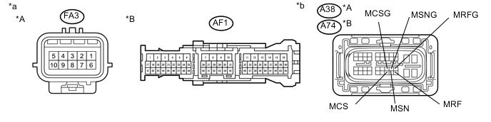
Standard Resistance (Check for Open) for LHD Tester Connection Switch Condition Specified Condition FA3-1 - A38-40 (MRF) Power switch off Below 1 Ω FA3-2 - A38-29 (MRFG) Power switch off Below 1 Ω FA3-3 - A38-39 (MSN) Power switch off Below 1 Ω FA3-4 - A38-28 (MSNG) Power switch off Below 1 Ω FA3-6 - A38-38 (MCS) Power switch off Below 1 Ω FA3-7 - A38-27 (MCSG) Power switch off Below 1 Ω for RHD Tester Connection Switch Condition Specified Condition AF1-58 - A74-40 (MRF) Power switch off Below 1 Ω AF1-59 - A74-29 (MRFG) Power switch off Below 1 Ω AF1-60 - A74-39 (MSN) Power switch off Below 1 Ω AF1-61 - A74-28 (MSNG) Power switch off Below 1 Ω AF1-38 - A74-38 (MCS) Power switch off Below 1 Ω AF1-57 - A74-27 (MCSG) Power switch off Below 1 Ω Standard Resistance (Check for Short) for LHD Tester Connection Switch Condition Specified Condition FA3-1 or A38-40 (MRF) - Body ground and other terminals Power switch off 10 kΩ or higher FA3-2 or A38-29 (MRFG) - Body ground and other terminals Power switch off 10 kΩ or higher FA3-3 or A38-39 (MSN) - Body ground and other terminals Power switch off 10 kΩ or higher FA3-4 or A38-28 (MSNG) - Body ground and other terminals Power switch off 10 kΩ or higher FA3-6 or A38-38 (MCS) - Body ground and other terminals Power switch off 10 kΩ or higher FA3-7 or A38-27 (MCSG) - Body ground and other terminals Power switch off 10 kΩ or higher for RHD Tester Connection Switch Condition Specified Condition AF1-58 or A74-40 (MRF) - Body ground and other terminals Power switch off 10 kΩ or higher AF1-59 or A74-29 (MRFG) - Body ground and other terminals Power switch off 10 kΩ or higher AF1-60 or A74-39 (MSN) - Body ground and other terminals Power switch off 10 kΩ or higher AF1-61 or A74-28 (MSNG) - Body ground and other terminals Power switch off 10 kΩ or higher AF1-62 or A74-38 (MCS) - Body ground and other terminals Power switch off 10 kΩ or higher AF1-57 or A74-27 (MCSG) - Body ground and other terminals Power switch off 10 kΩ or higher Tech Tips
Slightly shake the wire harness and connector vertically and horizontally, and check that the malfunction does not occur Click here.
Text in Illustration *A for LHD *B for RHD *a Front view of wire harness connector
(Junction Connector)
*b Front view of wire harness connector
(to Inverter with Converter Assembly)
-
Connect the inverter with converter assembly connector.
-
Connect the junction connector.
OK
REPAIR OR REPLACE HARNESS OR CONNECTOR (JUNCTION CONNECTOR - MOTOR RESOLVER)
NG
REPAIR OR REPLACE HARNESS OR CONNECTOR (JUNCTION CONNECTOR - INVERTER WITH CONVERTER ASSEMBLY)
-
-
CHECK CONNECTOR CONNECTION CONDITION (POWER MANAGEMENT CONTROL ECU CONNECTOR)
-
Text in Illustration *A for LHD *B for RHD Check the connector connections and contact pressure of the relevant terminals for the power management control ECU connectors Click here.
OK The connectors are connected securely and there are no contact pressure problems.
NG
CONNECT SECURELY
OK
-
-
CHECK CONNECTOR CONNECTION CONDITION (TRANSMISSION WIRE CONNECTOR)
-
Check the connection of the transmission wire connector Click here.
OK The connector is connected securely and there are no contact problems.
NG
CONNECT SECURELY
OK
-
-
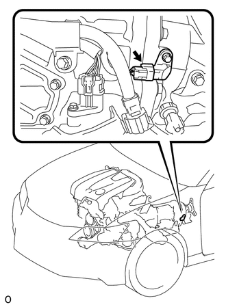
CHECK CONNECTOR CONNECTION CONDITION (OIL PUMP MOTOR CONTROLLER CONNECTOR)
Note
Before disconnecting the connectors, confirm that they are properly connected by checking that the locking claws are engaged and that the connectors cannot be pulled out.
-
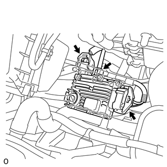
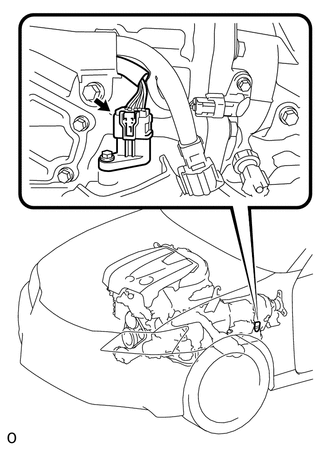
Check the connections of the oil pump motor controller connectors Click here.
OK The connectors are connected securely and there are no contact problems. Tech Tips
For connector A, when connecting it, insert it with the locking lever in the raised position. Rotate the lever downward and make sure that the connector is pulled into its socket. When the locking lever is in its fully closed position, a click will be heard as its locking claws engage. After the click is heard, pull up on the connector to confirm that it is properly connected.
NG
CONNECT SECURELY
OK
-
-
CHECK FUSIBLE LINK (OIL PMP)
-
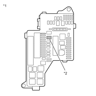
Text in Illustration *1 No. 1 Engine Room Relay Block and Junction Block Assembly *2 Fusible Link (OIL PMP) Check if there is an open circuit in the fusible link (OIL PMP) in the No. 1 engine room relay block and junction block assembly.
OK There is no open circuit in the fusible link (OIL PMP).
NG
REPLACE FUSIBLE LINK (OIL PMP)
OK
-
-
CHECK HYBRID VEHICLE TRANSMISSION ASSEMBLY (SOLENOID VALVE (SL1), SOLENOID VALVE (SL2) AND SOLENOID VALVE (SP))
-
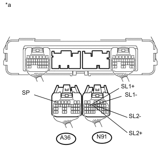
Text in Illustration *a Rear view of wire harness connector
(to Power Management Control ECU)
Disconnect the connector from the power management control ECU.
-
Measure the resistance according to the value(s) in the table below.
Standard Resistance Tester Connection Condition Specified Condition A36-7 (SP) - Body ground 68°F (20°C) 11 to 15 Ω Standard Resistance Tester Connection Condition Specified Condition N91-14 (SL1+) - N91-13 (SL1-) 68°F (20°C) 5.0 to 5.6 Ω N91-12 (SL2+) - N91-11 (SL2-) 68°F (20°C) 5.0 to 5.6 Ω -
Connect the power management control ECU connector.
NG
CHECK HARNESS AND CONNECTOR (POWER MANAGEMENT CONTROL ECU - TRANSMISSION WIRE) Click here
OK
-
-
CHECK RELAY (OIL PMP)
-
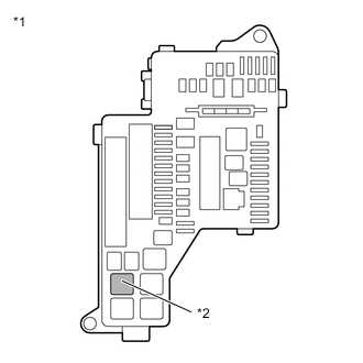
Text in Illustration *1 No. 1 Engine Room Relay Block and Junction Block Assembly *2 OIL PMP Relay Remove the OIL PMP relay from the No. 1 engine room relay block and junction block assembly.
-
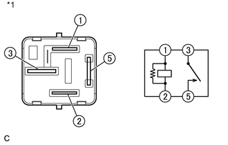
Text in Illustration *1 OIL PMP Relay Measure the resistance according to the value(s) in the table below.
Standard Resistance Tester Connection Condition Specified Condition 1 - 2 Always 151 to 203 Ω 3 - 5 Auxiliary battery voltage is not applied between terminals 1 and 2 10 kΩ or higher Auxiliary battery voltage is applied between terminals 1 and 2 Below 1 Ω -
Install the OIL PMP relay to the No. 1 engine room relay block and junction block assembly.
NG
REPLACE RELAY (OIL PMP)
OK
-
-
CHECK HARNESS AND CONNECTOR (POWER MANAGEMENT CONTROL ECU - OIL PUMP MOTOR CONTROLLER)
-
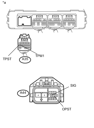
Text in Illustration *a Rear view of wire harness connector
(to Power Management Control ECU)
*b Front view of wire harness connector
(to Oil Pump Motor Controller)
Disconnect the connector from the power management control ECU.
-
Disconnect the connector from the oil pump motor controller.
-
Turn the power switch on (IG).
-
Measure the voltage according to the value(s) in the table below.
Standard Voltage Tester Connection Switch Condition Specified Condition A35-16 (TPM1) - Body ground Power switch on (IG) Below 1 V A35-17 (TPST) - Body ground Power switch on (IG) Below 1 V Note
Turning the power switch on (IG) with the power management control ECU and oil pump motor controller connectors disconnected causes other DTCs to be stored. Clear the DTCs after performing this inspection.
-
Turn the power switch off.
-
Measure the resistance according to the value(s) in the table below.
Standard Resistance Tester Connection Switch Condition Specified Condition A35-16 (TPM1) - A44-6 (SIG) Power switch off Below 1 Ω A35-17 (TPST) - A44-7 (OPST) Power switch off Below 1 Ω A35-16 (TPM1) - Body ground and other terminals Power switch off 10 kΩ or higher A35-17 (TPST) - Body ground and other terminals Power switch off 10 kΩ or higher -
Connect the power management control ECU connector.
-
Connect the oil pump motor controller connector.
NG
REPAIR OR REPLACE HARNESS OR CONNECTOR
OK
-
-
CHECK OIL WITH MOTOR PUMP ASSEMBLY
-
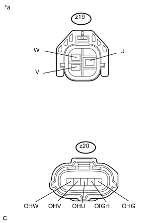
Text in Illustration *a Front view of wire harness connector
(to Oil Pump Motor Controller)
Disconnect the connectors from the oil pump motor controller.
-
Turn the power switch on (IG).
-
Measure the voltage according to the value(s) in the table below.
Standard Voltage Tester Connection Switch Condition Specified Condition Z19-1 (W) - Body ground Power switch on (IG) Below 1 V Z19-2 (U) - Body ground Power switch on (IG) Below 1 V Z19-3 (V) - Body ground Power switch on (IG) Below 1 V z20-1 (OHW) - Body ground Power switch on (IG) Below 1 V z20-2 (OHV) - Body ground Power switch on (IG) Below 1 V z20-3 (OHU) - Body ground Power switch on (IG) Below 1 V z20-4 (OIGH) - Body ground Power switch on (IG) Below 1 V z20-5 (OHG) - Body ground Power switch on (IG) Below 1 V Note
Turning the power switch on (IG) with the oil pump motor controller connectors disconnected causes other DTCs to be stored. Clear the DTCs after performing this inspection.
-
Turn the power switch off.
-
Measure the resistance according to the value(s) in the table below.
Standard Resistance Tester Connection Switch Condition Specified Condition z19-1 (W) - z19-2 (U) Power switch off Below 1 Ω z19-1 (W) - z19-3 (V) Power switch off Below 1 Ω z19-1 (W) - Body ground Power switch off 10 kΩ or higher z19-2 (U) - Body ground Power switch off 10 kΩ or higher z19-3 (V) - Body ground Power switch off 10 kΩ or higher z20-1 (OHW) - Body ground Power switch off 10 kΩ or higher z20-2 (OHV) - Body ground Power switch off 10 kΩ or higher z20-3 (OHU) - Body ground Power switch off 10 kΩ or higher z20-4 (OIGH) - Body ground Power switch off 10 kΩ or higher z20-5 (OHG) - Body ground Power switch off 10 kΩ or higher -
Connect the oil pump motor controller connector.
NG
REPLACE OIL WITH MOTOR PUMP ASSEMBLY Click here
OK
-
-
CHECK OIL PUMP MOTOR CONTROLLER (POWER SOURCE CIRCUIT)
-
Disconnect the connector from the oil pump motor controller.
-
Turn the power switch on (IG).
-
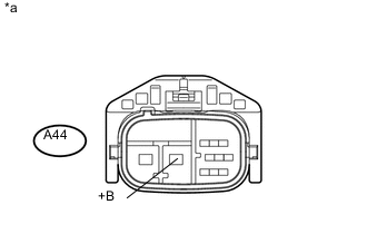
Text in Illustration *a Front view of wire harness connector
(to Oil Pump Motor Controller)
Measure the voltage according to the value(s) in the table below.
Standard Voltage Tester Connection Switch Condition Specified Condition A44-5 (+B) - Body ground Power switch on (IG) 11 to 14 V -
Turn the power switch off.
-
Text in Illustration *1 No. 1 Engine Room Relay Block and Junction Block Assembly *2 OIL PMP Relay Remove the OIL PMP relay from the No. 1 engine room relay block and junction block assembly.
-
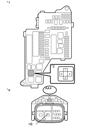
Text in Illustration *1 No. 1 Engine Room Relay Block and Junction Block Assembly *2 OIL PMP Relay *a Front view of wire harness connector
(to Oil Pump Motor Controller)
Measure the resistance according to the value(s) in the table below.
Standard Resistance Tester Connection Switch Condition Specified Condition 5 (OIL PMP relay) - A44-5 (+B) Power switch off Below 1 Ω 2 (OIL PMP relay) - Body ground Power switch off Below 1 Ω 5 (OIL PMP relay) - Body ground Power switch off 10 kΩ or higher -
Disconnect the connector from the power management control ECU.
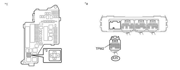
Text in Illustration *1 No. 1 Engine Room Relay Block and Junction Block Assembly *2 OIL PMP Relay *a Rear view of wire harness connector
(to Power Management Control ECU)
- - -
Turn the power switch off.
-
Measure the resistance according to the value(s) in the table below.
Standard Resistance Tester Connection Switch Condition Specified Condition 1 (OIL PMP relay) - A35-7 (TPM2) Power switch off Below 1 Ω 1 (OIL PMP relay) or A35-7 (TPM2) - Body ground Power switch off 10 kΩ or higher -
Connect the oil pump motor controller connector.
-
Install the OIL PMP relay to the No. 1 engine room relay block and junction block assembly.
-
Connect the power management control ECU connector.
NG
REPAIR OR REPLACE HARNESS OR CONNECTOR
OK
-
-
CHECK TRANSMISSION REVOLUTION SENSOR (SP2)
-
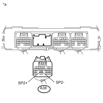
Text in Illustration *a Rear view of wire harness connector
(to Power Management Control ECU)
Disconnect the connector from the power management control ECU.
-
Measure the resistance according to the value(s) in the table below.
Standard Resistance Tester Connection Condition Specified Condition A36-25 (SP2+) - A36-24 (SP2-) Approximately 68°F (20°C) 560 to 680 Ω -
Connect the power management control ECU connector.
NG
CHECK CONNECTOR CONNECTION CONDITION (TRANSMISSION REVOLUTION SENSOR (SP2) CONNECTOR) Click here
OK
-
-
CHECK CONNECTOR CONNECTION CONDITION (INVERTER WITH CONVERTER ASSEMBLY CONNECTOR)
CAUTION:
Be sure to wear insulated gloves.
-
Check that the service plug grip is not installed.
Note
After removing the service plug grip, do not turn the power switch on (READY), unless instructed by the repair manual because this may cause a malfunction.
-
Check the connector connections and contact pressure of the low voltage connectors of the inverter with converter assembly Click here.
Note
Before disconnecting the connector, confirm that it is properly connected by checking that the locking claws are engaged and that the connector cannot be pulled out.
Text in Illustration *A for LHD *B for RHD OK The connectors are connected securely and there are no contact pressure problems. Tech Tips
When connecting the connector, insert it with the locking lever in the raised position. Rotate the lever downward and make sure that the connector is pulled into its socket. When the locking lever is in its fully closed position, a click will be heard as its locking claws engage. After the click is heard, pull up on the connector to confirm that it is properly connected.
NG
CONNECT SECURELY
OK
-
-
CHECK HARNESS AND CONNECTOR (INVERTER WITH CONVERTER ASSEMBLY - MOTOR RESOLVER)
CAUTION:
Be sure to wear insulated gloves.
-
Check that the service plug grip is not installed.
Note
After removing the service plug grip, do not turn the power switch on (READY), unless instructed by the repair manual because this may cause a malfunction.
-
Disconnect the connector from the inverter with converter assembly.
-
Connect the cable to the negative (-) auxiliary battery terminal.
-
Turn the power switch on (IG).
-
Text in Illustration *A for LHD *B for RHD *a Front view of wire harness connector
(to Inverter with Converter Assembly)
Measure the voltage according to the value(s) in the table below.
Standard Voltage for LHD Tester Connection Switch Condition Specified Condition A38-40 (MRF) - Body ground Power switch on (IG) Below 1 V A38-29 (MRFG) - Body ground Power switch on (IG) Below 1 V A38-39 (MSN) - Body ground Power switch on (IG) Below 1 V A38-28 (MSNG) - Body ground Power switch on (IG) Below 1 V A38-38 (MCS) - Body ground Power switch on (IG) Below 1 V A38-27 (MCSG) - Body ground Power switch on (IG) Below 1 V for RHD Tester Connection Switch Condition Specified Condition A74-40 (MRF) - Body ground Power switch on (IG) Below 1 V A74-29 (MRFG) - Body ground Power switch on (IG) Below 1 V A74-39 (MSN) - Body ground Power switch on (IG) Below 1 V A74-28 (MSNG) - Body ground Power switch on (IG) Below 1 V A74-38 (MCS) - Body ground Power switch on (IG) Below 1 V A74-27 (MCSG) - Body ground Power switch on (IG) Below 1 V Note
Turning the power switch on (IG) with the low voltage connector of the inverter with converter assembly disconnected causes other DTCs to be stored. Clear the DTCs after performing this inspection.
-
Turn the power switch off.
-
Disconnect the cable from the negative (-) auxiliary battery terminal.
-
Connect the inverter with converter assembly connector.
NG
REPAIR OR REPLACE HARNESS OR CONNECTOR
OK
-
-
CHECK MOTOR RESOLVER
CAUTION:
Be sure to wear insulated gloves.
-
Check that the service plug grip is not installed.
Note
After removing the service plug grip, do not turn the power switch on (READY), unless instructed by the repair manual because this may cause a malfunction.
-
Disconnect the connector from the inverter with converter assembly.
-
Text in Illustration *A for LHD *B for RHD *a Front view of wire harness connector
(to Inverter with Converter Assembly)
Measure the resistance according to the value(s) in the table below.
Standard Resistance (Check for Open) for LHD Tester Connection Switch Condition Specified Condition A38-40 (MRF) - A38-29 (MRFG) Power switch off 6.0 to 12.0 Ω A38-39 (MSN) - A38-28 (MSNG) Power switch off 12.5 to 24.5 Ω A38-38 (MCS) - A38-27 (MCSG) Power switch off 12.5 to 24.5 Ω for RHD Tester Connection Switch Condition Specified Condition A74-40 (MRF) - A74-29 (MRFG) Power switch off 6.0 to 12.0 Ω A74-39 (MSN) - A74-28 (MSNG) Power switch off 12.5 to 24.5 Ω A74-38 (MCS) - A74-27 (MCSG) Power switch off 12.5 to 24.5 Ω Standard Resistance (Check for Short) for LHD Tester Connection Switch Condition Specified Condition A38-40 (MRF) or A38-29 (MRFG) - Body ground and other terminals Power switch off 1 MΩ or higher A38-39 (MSN) or A38-28 (MSNG) - Body ground and other terminals Power switch off 1 MΩ or higher A38-38 (MCS) or A38-27 (MCSG) - Body ground and other terminals Power switch off 1 MΩ or higher for RHD Tester Connection Switch Condition Specified Condition A74-40 (MRF) or A74-29 (MRFG) - Body ground and other terminals Power switch off 1 MΩ or higher A74-39 (MSN) or A74-28 (MSNG) - Body ground and other terminals Power switch off 1 MΩ or higher A74-38 (MCS) or A74-27 (MCSG) - Body ground and other terminals Power switch off 1 MΩ or higher -
Connect the inverter with converter assembly connector.
NG
CHECK CONNECTOR CONNECTION CONDITION (MOTOR RESOLVER CONNECTOR) Click here
OK
-
-
CLEAR DTC
-
Connect the GTS to the DLC3.
-
Turn the power switch on (IG).
-
Enter the following menus: Powertrain / Hybrid Control / Trouble Codes.
-
Read and record the DTCs and freeze frame data.
-
Clear DTCs and freeze frame data.
-
Turn the power switch off.
NEXT
-
-
SIMULATION TEST
-
Connect the GTS to the DLC3.
-
Turn the power switch on (READY).
-
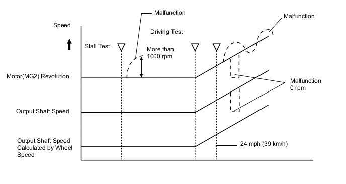
Enter the following menus: Powertrain / Hybrid Control / Data List / Motor(MG2) Revolution, Output Shaft Speed, Output Shaft Speed Calculated by Wheel Speed.
-
Perform a stall test and road test, and read the Data List.
Note
-
Before inspection, sufficiently warm up the engine.
-
Make sure to perform this procedure after the engine has been inspected and adjusted.
-
Do not perform a stall test for 5 or more seconds.
-
Perform a stall test on an asphalt surface or other place with a high friction coefficient (μ) in order to prevent wheel spin.
Tech Tips
-
When performing a road test, the vehicle speed should be 24 mph (39 km/h) or more.
-
Avoid sudden acceleration and deceleration during a road test.
OK The "Motor(MG2) Revolution" value in the Data List changes normally. The "Output Shaft Speed" and "Output Shaft Speed Calculated by Wheel Speed" values should be almost equal with a vehicle speed of 24 mph (39 km/h) or more. -
-
Turn the power switch off.
NG
REPLACE HYBRID VEHICLE TRANSMISSION ASSEMBLY Click here
OK
-
-
CHECK FOR INTERMITTENT PROBLEMS
NG
REPAIR OR REPLACE MALFUNCTIONING PARTS, COMPONENT AND AREA
OK
-
CHECK FLUID LEAKS
-
Check for fluid leaks from the hybrid vehicle transmission assembly.
OK There are no fluid leaks.
OK
REPLACE POWER MANAGEMENT CONTROL ECU Click here
NG
REPAIR OR REPLACE HYBRID VEHICLE TRANSMISSION ASSEMBLY Click here
-
-
CHECK HARNESS AND CONNECTOR (POWER MANAGEMENT CONTROL ECU - TRANSMISSION WIRE)
-
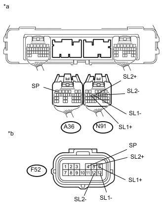
Text in Illustration *a Rear view of wire harness connector
(to Power Management Control ECU)
*b Front view of wire harness connector
(to Transmission Wire)
Disconnect the power management control ECU connector.
-
Disconnect the transmission wire connector.
-
Turn the power switch on (IG).
-
Measure the voltage according to the value(s) in the table below.
Standard Voltage Tester Connection Switch Condition Specified Condition A36-7 (SP) - Body ground Power switch on (IG) Below 1 V N91-13 (SL1-) - Body ground Power switch on (IG) Below 1 V N91-14 (SL1+) - Body ground Power switch on (IG) Below 1 V N91-11 (SL2-) - Body ground Power switch on (IG) Below 1 V N91-12 (SL2+) - Body ground Power switch on (IG) Below 1 V Note
Turning the power switch on (IG) with the power management control ECU connector disconnected causes other DTCs to be stored. Clear the DTCs after performing this inspection.
-
Turn the power switch off.
-
Measure the resistance according to the value(s) in the table below.
Standard Resistance Tester Connection Switch Condition Specified Condition A36-7 (SP) - F52-4 (SP) Power switch off Below 1 Ω N91-13 (SL1-) - F52-13 (SL1-) Power switch off Below 1 Ω N91-14 (SL1+) - F52-6 (SL1+) Power switch off Below 1 Ω N91-11 (SL2-) - F52-12 (SL2-) Power switch off Below 1 Ω N91-12 (SL2+) - F52-5 (SL2+) Power switch off Below 1 Ω A36-7 (SP) or F52-4 (SP) - Body ground and other terminals Power switch off 10 kΩ or higher N91-13 (SL1-) or F52-13 (SL1-) - Body ground and other terminals Power switch off 10 kΩ or higher N91-14 (SL1+) or F52-6 (SL1+) - Body ground and other terminals Power switch off 10 kΩ or higher N91-11 (SL2-) or F52-12 (SL2-) - Body ground and other terminals Power switch off 10 kΩ or higher N91-12 (SL2+) or F52-5 (SL2+) - Body ground and other terminals Power switch off 10 kΩ or higher -
Connect the power management control ECU connector.
-
Connect the transmission control switch connector.
OK
REPLACE HYBRID VEHICLE TRANSMISSION ASSEMBLY Click here
NG
REPAIR OR REPLACE HARNESS OR CONNECTOR
-
-
CHECK CONNECTOR CONNECTION CONDITION (TRANSMISSION REVOLUTION SENSOR (SP2) CONNECTOR)
-
Check the connection of the transmission revolution sensor (SP2) connector Click here.
OK The connector is connected securely and there are no contact problems.
NG
CONNECT SECURELY
OK
-
-
CHECK HARNESS AND CONNECTOR (TRANSMISSION REVOLUTION SENSOR (SP2) - POWER MANAGEMENT CONTROL ECU)
-
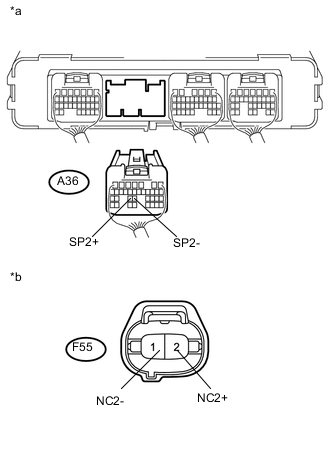
Text in Illustration *a Rear view of wire harness connector
(to Power Management Control ECU)
*b Front view of wire harness connector
(to Transmission Revolution Sensor (SP2))
Disconnect the power management control ECU connector.
-
Disconnect the transmission revolution sensor (SP2) connector.
-
Turn the power switch on (IG).
-
Measure the voltage according to the value(s) in the table below.
Standard Voltage Tester Connection Switch Condition Specified Condition A36-24 (SP2-) - Body ground Power switch on (IG) Below 1 V A36-25 (SP2+) - Body ground Power switch on (IG) Below 1 V Note
Turning the power switch on (IG) with the power management control ECU connector disconnected causes other DTCs to be stored. Clear the DTCs after performing this inspection.
-
Turn the power switch off.
-
Measure the resistance according to the value(s) in the table below.
Standard Resistance Tester Connection Switch Condition Specified Condition A36-24 (SP2-) - F55-1 (NC2-) Power switch off Below 1 Ω A36-25 (SP2+) - F55-2 (NC2+) Power switch off Below 1 Ω A36-24 (SP2-) or F55-1 (NC2-) - Body ground and other terminals Power switch off 10 kΩ or higher A36-25 (SP2+) or F55-2 (NC2+) - Body ground and other terminals Power switch off 10 kΩ or higher Tech Tips
The transmission revolution sensor is not available separately. If it requires replacement, replace the hybrid vehicle transmission assembly.
-
Connect the power management control ECU connector.
-
Connect the transmission revolution sensor (SP2) connector.
OK
REPLACE HYBRID VEHICLE TRANSMISSION ASSEMBLY Click here
NG
REPAIR OR REPLACE HARNESS OR CONNECTOR
-
-
CHECK CONNECTOR CONNECTION CONDITION (MOTOR RESOLVER CONNECTOR)
-
Check the connection condition of the motor resolver connector and the contact pressure of each terminal. Check the terminals for deformation, and check the connector for water ingress and foreign matter Click here.
OK The connector is connected securely and there are no contact problems. Note
If the terminals connect poorly, are damaged, or contain water or foreign matter, repair or replace the wire harness or connector.
NG
CONNECT SECURELY
OK
-
-
CHECK HYBRID VEHICLE TRANSMISSION ASSEMBLY (MOTOR RESOLVER)
-
Disconnect the resolver connector.
-
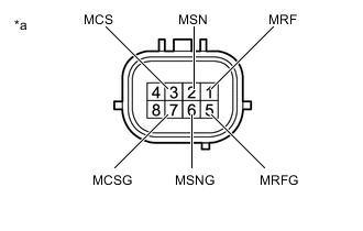
*a Component without harness connected
(Motor Resolver (Hybrid Vehicle Transmission Assembly))
Measure the resistance according to the value(s) in the table below.
Standard Resistance (Check for Open) Tester Connection Condition Specified Condition 1 (MRF) - 5 (MRFG) Power switch off 6.0 to 12.0 Ω 2 (MSN) - 6 (MSNG) Power switch off 12.5 to 24.5 Ω 3 (MCS) - 7 (MCSG) Power switch off 12.5 to 24.5 Ω Tech Tips
To correct the variation of the measured resistance due to temperature, use the following formula to calculate the resistance at 20°C (68°F).
R20 = Rt / {1 + 0.00393 X (T - 20)}
The calculation is based on the following:
R20: Resistance at 20°C (68°F) (mΩ)
Rt: Measured resistance (mΩ)
T: Temperature when the resistance is measured (°C (°F).)
Standard Resistance (Check for Short) Tester Connection Condition Specified Condition 1 (MRF) - Body ground and other terminals (except 5 (MRFG)) Power switch off 1 MΩ or higher 5 (MRFG) - Body ground and other terminals (except 1 (MRF)) Power switch off 1 MΩ or higher 2 (MSN) - Body ground and other terminals (except 6 (MSNG)) Power switch off 1 MΩ or higher 6 (MSNG) - Body ground and other terminals (except 2 (MSN)) Power switch off 1 MΩ or higher 3 (MCS) - Body ground and other terminals (except 7 (MCSG)) Power switch off 1 MΩ or higher 7 (MCSG) - Body ground and other terminals (except 3 (MCS)) Power switch off 1 MΩ or higher -
Reconnect the resolver connector.
Result Proceed to OK NG
OK
REPAIR OR REPLACE HARNESS OR CONNECTOR
NG
REPLACE HYBRID VEHICLE TRANSMISSION ASSEMBLY Click here
-