HYBRID CONTROL SYSTEM, Diagnostic DTC:P0711-883
| DTC Code | DTC Name |
|---|---|
| P0711-883 | Transmission Fluid Temperature Sensor Circuit Range / Performance |
DESCRIPTION
Refer to the description for DTC P0712-856 Click here.
| DTC No. | INF Code | DTC Detection Condition | Trouble Area |
|---|---|---|---|
| P0711 | 883 | As a result of comparing the fluid temperature and coolant temperature with the power switch on (READY), the fluid temperature exceeds a specified level while the coolant temperature is less than the specified level. (2 trip detection) |
|
Tech Tips
DTC P0711-833 will be set if the engine coolant temperature changes from 95°F (35°C) or less to 140°F (60°C) after the power switch is turned on (READY).
WIRING DIAGRAM
Refer to the wiring diagram for DTC P0712-856 Click here.
PROCEDURE
-
CHECK DTC OUTPUT (HYBRID CONTROL)
-
Connect the GTS to the DLC3.
-
Turn the power switch on (IG).
-
Enter the following menus: Powertrain / Hybrid Control / Trouble Codes.
-
Check if DTCs are output.
Result Result Proceed to P0711-883 only is output. A Any of the following DTCs are also output. B DTC No. Relevant Diagnosis P0712-856 Transmission Fluid Temperature Sensor "A" Circuit Low Input P0713-857 Transmission Fluid Temperature Sensor "A" Circuit High Input -
Turn the power switch off.
B 
GO TO DTC CHART (HYBRID CONTROL SYSTEM) Click here
A 
-
-
CHECK CONNECTOR CONNECTION CONDITION (POWER MANAGEMENT CONTROL ECU CONNECTOR)
-
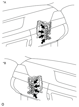
Text in Illustration *A for LHD *B for RHD Check the connector connections and contact pressure of the relevant terminals for the power management control ECU connectors Click here.
OK The connectors are connected securely and there are no contact pressure problems.
NG
CONNECT SECURELY
OK
-
-
CHECK TRANSMISSION WIRE (TRANSMISSION FLUID TEMPERATURE SENSOR)
-
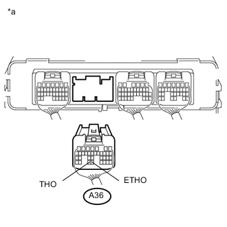
Text in Illustration *a Rear view of wire harness connector
(to Power Management Control ECU)
Disconnect the connector from the power management control ECU.
-
Measure the resistance according to the value(s) in the table below.
Standard Resistance Tester Connection Condition Specified Condition A36-33 (THO) - A36-32 (ETHO) 50°F (10°C) 5.0 to 8.0 kΩ A36-33 (THO) - A36-32 (ETHO) 230°F (110°C) 0.22 to 0.28 kΩ -
Connect the power management control ECU connector.
NG 
CHECK CONNECTOR CONNECTION CONDITION (TRANSMISSION WIRE CONNECTOR) Click here
OK
-
-
CLEAR DTC
-
Connect the GTS to the DLC3.
-
Turn the power switch on (IG).
-
Enter the following menus: Powertrain / Hybrid Control / Trouble Codes.
-
Read and record the DTCs and freeze frame data.
-
Clear DTCs and freeze frame data.
-
Turn the power switch off.
NEXT
-
-
READ VALUE USING GTS (T/M OIL TEMPERATURE)
-
Connect the GTS to the DLC3.
-
Turn the power switch on (IG).
-
Enter the following menus: Powertrain / Hybrid Control / Data List / T/M Oil Temperature.
-
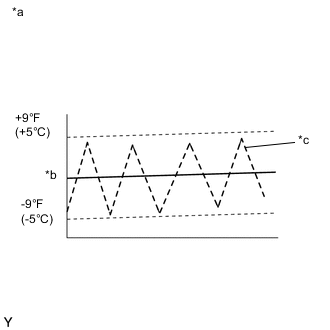
Text in Illustration *a T/M TEMP *b Normal *c Malfunction Read the Data List.
OK The T/M Oil Temperature value is within the normal range and does not fluctuate. -
Turn the power switch off.
NG
REPLACE TRANSMISSION WIRE Click here
OK
-
-
CHECK FOR INTERMITTENT PROBLEMS
NG
REPAIR OR REPLACE MALFUNCTIONING PARTS, COMPONENT AND AREA
OK
-
CHECK FLUID LEAKS
-
Check for fluid leaks from the hybrid vehicle transmission assembly.
OK There are no fluid leaks.
OK
REPLACE POWER MANAGEMENT CONTROL ECU Click here
NG
REPAIR OR REPLACE HYBRID VEHICLE TRANSMISSION ASSEMBLY Click here
-
-
CHECK CONNECTOR CONNECTION CONDITION (TRANSMISSION WIRE CONNECTOR)
-
Check the connection of the transmission wire connector Click here.
OK The connector is connected securely and there are no contact problems.
NG
CONNECT SECURELY
OK
-
-
CHECK HARNESS AND CONNECTOR (POWER MANAGEMENT CONTROL ECU - TRANSMISSION WIRE)
-
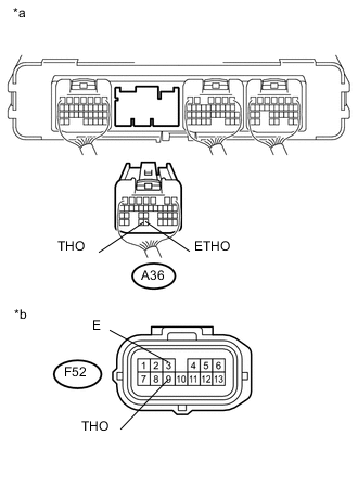
Text in Illustration *a Rear view of wire harness connector
(to Power Management Control ECU)
*b Front view of wire harness connector
(to Transmission Wire)
Disconnect the power management control ECU connector.
-
Disconnect the transmission wire connector.
-
Turn the power switch on (IG).
-
Measure the voltage according to the value(s) in the table below.
Standard Voltage Tester Connection Switch Condition Specified Condition A36-33 (THO) - Body ground Power switch on (IG) Below 1 V A36-32 (ETHO) - Body ground Power switch on (IG) Below 1 V Note
Turning the power switch on (IG) with the power management control ECU connectors disconnected causes other DTCs to be stored. Clear the DTCs after performing this inspection.
-
Turn the power switch off.
-
Measure the resistance according to the value(s) in the table below.
Standard Resistance Tester Connection Switch Condition Specified Condition A36-33 (THO) - F52-9 (THO) Power switch off Below 1 Ω A36-32 (ETHO) - F52-3 (E) Power switch off Below 1 Ω A36-33 (THO) or F52-9 (THO) - Body ground and other terminals Power switch off 10 kΩ or higher A36-32 (ETHO) or F52-3 (E) - Body ground and other terminals Power switch off 10 kΩ or higher -
Connect the power management control ECU connector.
-
Connect the transmission wire connector.
OK
REPLACE TRANSMISSION WIRE Click here
NG
REPAIR OR REPLACE HARNESS OR CONNECTOR
-