HYBRID CONTROL SYSTEM TERMINALS OF ECU
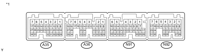
| *1 | Power Management Control ECU | - | - |
| Terminal No. (Symbol) |
Wiring Color | Terminal Description | Condition | Specified Condition |
|---|---|---|---|---|
| A35-1 (+B2) - N91-6 (E1) | W - W-B | Power source | Power switch on (IG) | 11 to 14 V |
| A35-2 (WP) - N91-6 (E1) | P - W-B | A/C WP relay signal | Power switch on (READY) | 0 to 2 V |
| A35-4 (MREL) - N91-6 (E1) | G - W-B | Main relay | Power switch on (IG) | 11 to 14 V |
| A35-5 (FCTL) - N91-6 (E1) | V - W-B | Cooling fan relay | Power switch on (IG) | 11 to 14 V |
| A35-6 (ST1-) - N91-6 (E1) | GR - W-B | Brake cancel switch | Power switch on (IG), brake pedal depressed | 0 to 1.5 V |
| Power switch on (IG), brake pedal released | 11 to 14 V | |||
| A35-7 (TPM2) - N91-6 (E1) | L - W-B | Oil pump motor | Power switch on (IG) | 11 to 14 V |
| A35-9 (PSFT) - N91-6 (E1) | R - W-B | Shift lever position sensor power source | Power switch on (ACC) | 11 to 14 V |
| A35-10 (ACCI) - N91-6 (E1) | GR - W-B | Power source | Power switch on (ACC) | 11 to 14 V |
| A35-12 (NIWP) - N91-6 (E1) | B - W-B | Inverter water pump with motor assembly signal | Power switch on (READY) | Pulse generation (Waveform 2) |
| A35-13 (IWP) - N91-6 (E1) | Y - W-B | Inverter water pump with motor assembly signal | Power switch on (READY) | Pulse generation (Waveform 2) |
| A35-14 (VLO) - N91-6 (E1) | SB - W-B | DC/DC operation monitor/voltage change signal | Power switch on (IG) | Pulse generation (Waveform 1) |
| A35-16 (TPM1) - N91-6 (E1) | B - W-B | Oil pump motor | Power switch on (READY) | Pulse generation (Waveform 14) |
| A35-17 (TPST) - N91-6 (E1) | W - W-B | Oil pump motor | Power switch on (READY) | Pulse generation (Waveform 15) |
| A35-19 (GI) - N91-6 (E1) | W - W-B | Camshaft position sensor signal | Power switch on (READY), with engine running | Pulse generation (Waveform 3) |
| A35-20 (MTH-) - N91-6 (E1) | W - W-B | Communication signal from MG ECU to power management control ECU | Power switch on (READY) | Pulse generation (Waveform 8) |
| A35-21 (MTH+) - N91-6 (E1) | B - W-B | Communication signal from MG ECU to power management control ECU | Power switch on (READY) | Pulse generation (Waveform 8) |
| A35-22 (ILK) - N91-6 (E1) | L - W-B | Interlock switch | Power switch on (IG), connector cover assembly, inverter terminal cover, No. 4 floor wire (air conditioning harness)*1, air conditioning harness*2 and service plug grip installed correctly | 0 to 1.5 V |
| Power switch on (IG), connector cover assembly, inverter terminal cover, No. 4 floor wire (air conditioning harness)*1, air conditioning harness*2 or service plug grip not installed | 11 to 14 V | |||
| A35-23 (NODD) - N91-6 (E1) | GR - W-B | DC/DC operation | DC/DC converter operating normally | 5 to 7 V |
| DC/DC converter not operating normally | 2 to 4 V | |||
| DC/DC converter operation prohibited | 0.1 to 0.5 V | |||
| A35-28 (CLK-) - N91-6 (E1) | W - W-B | MG communication clock signal | Power switch on (READY) | Pulse generation (Waveform 6) |
| A35-29 (CLK+) - N91-6 (E1) | B - W-B | MG communication clock signal | Power switch on (READY) | Pulse generation (Waveform 6) |
| A35-30 (HSDN) - N91-6 (E1) | B - W-B | MG ECU shutdown signal | Power switch on (READY) | 0 to 1.5 V |
| A35-31 (REQ-) - N91-6 (E1) | W - W-B | MG ECU communication request signal | Power switch on (READY) | Pulse generation (Waveform 9) |
| A35-32 (REQ+) - N91-6 (E1) | B - W-B | MG ECU communication request signal | Power switch on (READY) | Pulse generation (Waveform 9) |
| A35-33 (HTM-) - N91-6 (E1) | W - W-B | Communication signal from power management control ECU to MG ECU | Power switch on (READY) | Pulse generation (Waveform 7) |
| A35-34 (HTM+) - N91-6 (E1) | B - W-B | Communication signal from power management control ECU to MG ECU | Power switch on (READY) | Pulse generation (Waveform 7) |
| A36-1 (IG2) - N91-6 (E1) | B - W-B*1 V - W-B*2 |
Power source | Power switch on (IG) | 11 to 14 V |
| A36-2 (IG2D) - N91-6 (E1) | L - W-B | IG2 relay | Power switch on (IG) | 11 to 14 V |
| A36-3 (+B1) - N91-6 (E1) | W - W-B | Power source | Power switch on (IG) | 11 to 14 V |
| A36-4 (PB3) - N91-6 (E1) | V - W-B | Pressure switch 3 | Power switch on (READY) | 11 to 14 V |
| A36-6 (PB1) - N91-6 (E1) | G-R - W-B*1 R - W-B*2 |
Pressure switch 1 | Power switch on (READY) | 11 to 14 V |
| A36-7 (SP) - N91-6 (E1) | G - W-B | SP solenoid valve signal | During Active Test | 11 to 14 V |
| A36-8 (FD) - N91-6 (E1) | P - W-B | Shift lever position signal | Power switch on (IG), shift lever in D or B | 11 to 14 V |
| Power switch on (IG), shift lever not in D or B | 0 to 1.5 V | |||
| A36-9 (RV) - N91-6 (E1) | GR - W-B | Shift lever position signal | Power switch on (IG), shift lever in R | 11 to 14 V |
| Power switch on (IG), shift lever not in R | 0 to 1.5 V | |||
| A36-10 (D) - N91-6 (E1) | L - W-B | Shift lever position signal | Power switch on (IG), shift lever in D | 11 to 14 V |
| Power switch on (IG), shift lever not in D | 0 to 1.5 V | |||
| A36-11 (N) - N91-6 (E1) | Y - W-B | Shift lever position signal | Power switch on (IG), shift lever in N | 11 to 14 V |
| Power switch on (IG), shift lever not in N | 1.2 to 2.8 V | |||
| A36-13 (R) - N91-6 (E1) | W - W-B | Shift lever position signal | Power switch on (IG), shift lever in R | 11 to 14 V |
| Power switch on (IG), shift lever not in R | 0 to 1.5 V | |||
| A36-14 (P) - N91-6 (E1) | G - W-B | Shift lever position signal | Power switch on (IG), shift lever in P | 11 to 14 V |
| Power switch on (IG), shift lever not in P | 0 to 1.5 V | |||
| A36-15 (MJ) - N91-6 (E1) | B - W-B | Shift lever position signal | Power switch on (IG), shift lever in P, R, N, D or B | 11 to 14 V |
| A36-16 (CLK) - N91-6 (E1) | Y - W-B | A/C communication signal | Power switch on (READY), air conditioning system stopped | Pulse generation (Waveform 4) |
| A36-17 (ITE) - N91-6 (E1) | W - W-B | A/C communication signal | Power switch on (READY), air conditioning system stopped | Pulse generation (Waveform 4) |
| A36-18 (ETI) - N91-6 (E1) | V - W-B | A/C communication signal | Power switch on (READY), air conditioning system stopped | Pulse generation (Waveform 4) |
| A36-19 (STB) - N91-6 (E1) | LG - W-B | A/C communication signal | Power switch on (READY), air conditioning system stopped | Pulse generation (Waveform 4) |
| A36-22 (VPA2) - A36-20 (EP2) | V - Y | Accelerator pedal sensor assembly (for accelerator pedal position detection) | Power switch on (IG), accelerator pedal released | 1.0 to 2.2 V |
| Power switch on (IG), engine stopped, shift lever in P, accelerator pedal fully depressed | 3.4 to 5.3 V | |||
| A36-23 (VPA1) - A36-21 (EP1) | R - W | Accelerator pedal sensor assembly (for accelerator pedal position detection) | Power switch on (IG), accelerator pedal released | 0.4 to 1.4 V |
| Power switch on (IG), engine stopped, shift lever in P, accelerator pedal fully depressed | 2.6 to 4.5 V | |||
| A36-25 (SP2+) - A36-24(SP2-) | L - Y | Transmission revolution sensor signal | Driving at approximately 34 mph (55 km/h) with power switch on (READY) | Pulse generation (Waveform 16) |
| A36-27 (GMT) - A36-26 (GMTG) | L - R | Generator temperature sensor | Power switch on (IG), temperature 25°C (77°F) | 3.6 to 4.6 V |
| Power switch on (IG), temperature 60°C (140°F) | 2.2 to 3.2 V | |||
| A36-29 (VCP1) - A36-21 (EP1) | G - W | Accelerator pedal sensor assembly power source (for VPA1) | Power switch on (IG) | 4.5 to 5.5 V |
| A36-30 (VCP2) - A36-20 (EP2) | B - Y | Accelerator pedal sensor assembly power source (for VPA2) | Power switch on (IG) | 4.5 to 5.5 V |
| A36-31 (TOPM) - A36-32 (ETHO) | P - BR | Oil pump motor temperature sensor | Power switch on (IG), temperature 77°F (25°C) | 3.5 to 4.2 V |
| A36-33 (THO) - A36-32 (ETHO) | GR - BR | Transmission fluid temperature sensor | Power switch on (IG), temperature 77°F (25°C) | 2.2 to 2.8 V |
| A36-35 (MMT) - A36-34 (MMTG) | P - B | Motor temperature sensor | Power switch on (IG), temperature 25°C (77°F) | 3.6 to 4.6 V |
| Power switch on (IG), temperature 60°C (140°F) | 2.2 to 3.2 V | |||
| N91-1 (AM22) - N91-6 (E1) | P - W-B | Constant power source | Power switch on (IG) | 11 to 14 V |
| Power switch on (READY) | 11 to 15.5 V | |||
| N91-2 (SMRG) - N91-5 (E01) | P - W-B | System main relay operation signal | Power switch on (IG)→Power switch on (READY) | Pulse generation (Waveform 10) |
| N91-3 (SMRP) - N91-5 (E01) | L - W-B | System main relay operation signal | Power switch on (IG)→Power switch on (READY) | Pulse generation (Waveform 10) |
| N91-4 (SMRB) - N91-5 (E01) | LG - W-B | System main relay operation signal | Power switch on (IG)→Power switch on (READY) | Pulse generation (Waveform 10) |
| N91-7 (SSW1) - N91-6 (E1) | V - W-B | Power switch | Power switch pressed and held | 0 to 1.5 V |
| N91-8 (BL) - N91-6 (E1) | R - W-B | Back-up light | Power switch on (IG), shift lever in R | 11 to 14 V |
| N91-9 (KD) - N91-6 (E1) | B - W-B | Kick-down switch signal | Power switch on (IG) and accelerator pedal is depressed | Below 1 V |
| Power switch on (IG) and accelerator pedal is released | 11 to 14 V | |||
| N91-12 (SL2+) - N91-11 (SL2-) | P - V | SL2 solenoid valve signal | During Active Test | Pulse generation (Waveform 17) |
| N91-14 (SL1+) - N91-13 (SL1-) | G - L | SL1 solenoid valve signal | During Active Test | Pulse generation (Waveform 18) |
| N91-16 (SPDI) - N91-6 (E1) | SB - W-B | Vehicle speed signal | Driving at approximately 20 km/h (12 mph) with power switch on (READY) | Pulse generation (Waveform 11) |
| N91-17 (SI0) - N91-6 (E1) | L - W-B | HV battery blower fan operation signal | Power switch on (IG), during Active Test | Pulse generation (Waveform 5) |
| N91-18 (SI1) - N91-6 (E1) | Y - W-B | HV battery blower fan operation signal | Power switch on (IG), during Active Test | Pulse generation (Waveform 5) |
| N91-20 (INDM) - N91-6 (E1) | SB - W-B | Shift position indicator signal | Power switch on (IG), shift lever in S | 0 to 3.2 V |
| Power switch on (IG), shift lever not in S | 11 to 14 V | |||
| N91-22 (INDD) - N91-6 (E1) | L - W-B | Shift position indicator signal | Power switch on (IG), shift lever in D | 0 to 3.2 V |
| Power switch on (IG), shift lever not in D | 11 to 14 V | |||
| N91-24 (PTO1) - N91-23 (EPT1) | LG - GR | Oil pressure sensor | Power switch on (READY) | 0.4 to 4.7 V |
| N91-25 (VPT1) - N91-23 (EPT1) | B - GR | Oil pressure sensor | Power switch on (IG) | 4.75 to 5.25 V |
| N91-27 (THB) - N91-26 (ETHB) | W - P | Auxiliary battery temperature | Power switch on (IG), auxiliary battery temperature 25°C (77°F) | 1.7 to 2.3 V |
| Power switch on (IG), auxiliary battery temperature 60°C (140°F) | 0.6 to 0.9 V | |||
| N91-29 (BTH-) - N91-6 (E1) | W - W-B | Communication signal from battery smart unit to power management control ECU | Power switch on (IG) | Pulse generation (Waveform 13) |
| N91-30 (BTH+) - N91-6 (E1) | B - W-B | Communication signal from battery smart unit to power management control ECU | Power switch on (IG) | Pulse generation (Waveform 13) |
| N91-31 (INDN) - N91-6 (E1) | Y - W-B | Shift position indicator signal | Power switch on (IG), shift lever in N | 0 to 3.2 V |
| Power switch on (IG), shift lever not in N | 11 to 14 V | |||
| N91-32 (INDR) - N91-6 (E1) | G - W-B | Shift position indicator signal | Power switch on (IG), shift lever in R | 0 to 3.2 V |
| Power switch on (IG), shift lever not in R | 11 to 14 V | |||
| N91-33 (INDP) - N91-6 (E1) | R - W-B | Shift position indicator signal | Power switch on (IG), shift lever in P | 0 to 3.2 V |
| Power switch on (IG), shift lever not in P | 11 to 14 V | |||
| N91-34 (CA2L) - N91-6 (E1) | LG - W-B | CAN communication signal | Power switch on (IG) | Pulse generation (Waveform 19) |
| N91-35 (CA2H) - N91-6 (E1) | L - W-B*1 V - W-B*2 |
CAN communication signal | Power switch on (IG) | Pulse generation (Waveform 19) |
| N92-1 (ACCD) - N91-6 (E1) | B - W-B | ACC relay | Power switch on (ACC) | 11 to 14 V |
| N92-2 (IG1D) - N91-6 (E1) | B - W-B | IG1 relay | Power switch on (IG) | 11 to 14 V |
| N92-7 (AM21) - N91-6 (E1) | P - W-B | Constant power source | Power switch on (IG) | 11 to 14 V |
| Power switch on (READY) | 11 to 15.5 V | |||
| N92-8 (TC) - N91-6 (E1) | W - W-B | Diagnosis terminal | Power switch on (IG) | 11 to 14 V |
| N92-9 (EVSW) - N91-6 (E1) | B - W-B | EV mode switch (combination switch assembly) signal | Power switch on (IG), EV mode switch (combination switch assembly) not operated | 11 to 14 V |
| Power switch on (IG), EV mode switch (combination switch assembly) operated | 0 to 1.5 V | |||
| N92-10 (STP) - N91-6 (E1) | G - W-B | Stop light switch | Brake pedal depressed | 11 to 14 V |
| Brake pedal released | 0 to 1.5 V | |||
| N92-11 (LIN2) - N91-6 (E1) | P - W-B | LIN communication signal | Power switch on (IG) | Pulse generation |
| N92-13 (ABFS) - N91-6 (E1) | Y - W-B | Airbag activation signal | Power switch on (READY) | Pulse generation (Waveform 12) |
| N92-17 (SSW2) - N91-6 (E1) | G - W-B | Power switch | Power switch pressed and held | 0 to 1.5 V |
| N92-20 (SFTD) - N91-6 (E1) | W - W-B | Transmission control | Power switch on (IG), shift lever in S | 11 to 14 V |
| Power switch on (IG), shift lever in (-) | 0 to 1.5 V | |||
| N92-21 (SFTU) - N91-6 (E1) | Y - W-B | Transmission control | Power switch on (IG), shift lever in S | 11 to 14 V |
| Power switch on (IG), shift lever in (+) | 0 to 1.5 V | |||
| N92-22 (M) - N91-6 (E1) | R - W-B | Transmission control | Power switch on (IG), shift lever in S | 11 to 14 V |
| Power switch on (IG), shift lever not in S | 0 to 1.5 V | |||
| N92-24 (CA1L) - N91-6 (E1) | W - W-B | CAN communication signal | Power switch on (IG) | Pulse generation (Waveform 20) |
| N92-25 (CA1H) - N91-6 (E1) | P - W-B | CAN communication signal | Power switch on (IG) | Pulse generation (Waveform 20) |
| N92-30 (CA3N) - N91-6 (E1) | W - W-B | CAN communication signal | Power switch on (IG) | Pulse generation (Waveform 21) |
| N92-31 (CA3P) - N91-6 (E1) | R - W-B | CAN communication signal | Power switch on (IG) | Pulse generation (Waveform 21) |
-
*1: for LHD
-
*2: for RHD
-
Oscilloscope waveforms
Tech Tips
Oscilloscope waveform samples are provided here for informational purposes. Noise and fluttering waveforms have been omitted.
-
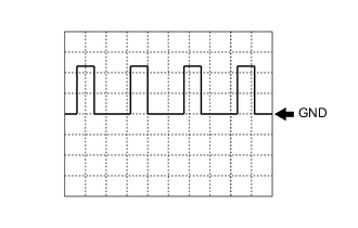
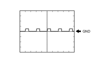
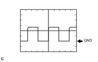
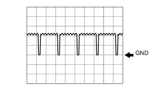
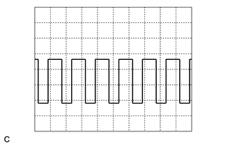
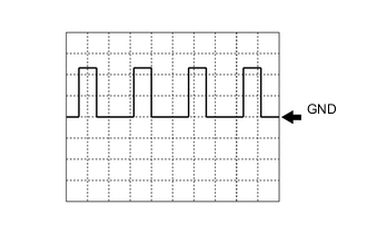
Waveform 1 (DC/DC operation monitor/voltage change signal)
Item Content Terminal A35-14 (VLO) - N91-6 (E1) Equipment Setting 5 V/DIV., 50 ms./DIV. Condition Power switch on (IG) Tech Tips
The cycle will vary depending on the specified voltage of the hybrid vehicle converter.
-
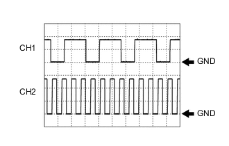
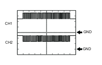
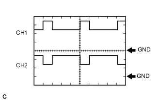
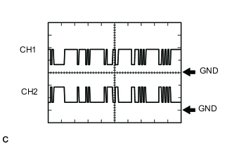
Waveform 2 (inverter water pump with motor assembly signal)
Item Content Terminal CH1: A35-13 (IWP) - N91-6 (E1)
CH2: A35-12 (NIWP) - N91-6 (E1)
Equipment Setting 5 V/DIV., 50 ms./DIV. Condition Power switch on (READY) -
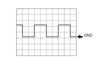
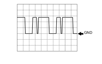
Waveform 3 (camshaft position sensor signal)
Item Content Terminal A35-19 (GI) - N91-6 (E1) Equipment Setting 5 V/DIV., 20 ms./DIV. Condition Power switch on (READY), with engine running Tech Tips
The pulse cycle becomes shorter as the engine speed increases.
-
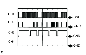
Waveform 4 (A/C communication signal)
Item Content Terminal CH1: A36-16 (CLK) - N91-6 (E1)
CH2: A36-17 (ITE) - N91-6 (E1)
CH3: A36-18 (ETI) - N91-6 (E1)
CH4: A36-19 (STB) - N91-6 (E1)
Equipment Setting 10 V/DIV., 100 ms./DIV. Condition Power switch on (READY), air conditioning system stopped Tech Tips
The waveform will vary depending on the content of the digital communication (digital signal).
-
Waveform 5 (HV battery blower fan operation signal)
Item Content Terminal N91-17 (SI0) - N91-6 (E1)
N91-18 (SI1) - N91-6 (E1)
Equipment Setting 10 V/DIV., 1 ms./DIV. Condition Power switch on (IG), during Active Test Tech Tips
The waveform will vary depending on the content of the digital communication (digital signal).
-
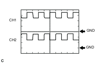
Waveform 6 (MG communication clock signal)
Item Content Terminal CH1: A35-29 (CLK+) - N91-6 (E1)
CH2: A35-28 (CLK-) - N91-6 (E1)
Equipment Setting 1 V/DIV., 1 μs./DIV. Condition Power switch on (READY) -
Waveform 7 (communication signal from power management control ECU to MG ECU)
Item Content Terminal CH1: A35-34 (HTM+) - N91-6 (E1)
CH2: A35-33 (HTM-) - N91-6 (E1)
Equipment Setting 1 V/DIV., 200 μs./DIV. Condition Power switch on (READY) Tech Tips
The waveform will vary depending on the content of the digital communication (digital signal).
-
Waveform 8 (communication signal from MG ECU to power management control ECU)
Item Content Terminal CH1: A35-21 (MTH+) - N91-6 (E1)
CH2: A35-20 (MTH-) - N91-6 (E1)
Equipment Setting 1 V/DIV., 200 μs./DIV. Condition Power switch on (READY) Tech Tips
The waveform will vary depending on the content of the digital communication (digital signal).
-
Waveform 9 (MG ECU communication request signal)
Item Content Terminal CH1: A35-32 (REQ+) - N91-6 (E1)
CH2: A35-31 (REQ-) - N91-6 (E1)
Equipment Setting 1 V/DIV., 1 ms./DIV. Condition Power switch on (READY) -
Waveform 10 (system main relay operation signal)
Item Content Terminal CH1: N91-3 (SMRP) - N91-5 (E01)
CH2: N91-4 (SMRB) - N91-5 (E01)
CH3: N91-2 (SMRG) - N91-5 (E01)
Equipment Setting 10 V/DIV., 200 ms./DIV. Condition Power switch on (IG) → Power switch on (READY) -
Waveform 11 (vehicle speed signal)
Item Content Terminal N91-16 (SPDI) - N91-6 (E1) Equipment Setting 5 V/DIV., 20 ms./DIV. Condition Driving at approximately 20 km/h (12 mph) with power switch on (READY) Tech Tips
The higher the vehicle speed, the shorter the cycle.
-
Waveform 12 (airbag activation signal)
Item Content Terminal N92-13 (ABFS) - N91-6 (E1) Equipment Setting 5 V/DIV., 500 ms./DIV. Condition Power switch on (READY) -
Waveform 13 (communication signal from battery smart unit to power management control ECU)
Item Content Terminal CH1: N91-30 (BTH+) - N91-6 (E1)
CH2: N91-29 (BTH-) - N91-6 (E1)
Equipment Setting 2 V/DIV., 500 μs./DIV. Condition Power switch on (IG) Tech Tips
The waveform will vary depending on the content of the digital communication (digital signal).
-
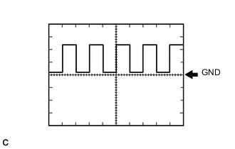
Waveform 14 (oil pump motor signal)
Item Content Terminal A35-16 (TPM1) - N91-6 (E1) Equipment Setting 5 V/DIV., 500 μs./DIV. Condition Power switch on (IG) -
Waveform 15 (oil pump motor signal)
Item Content Terminal A35-17 (TPST) - N91-6 (E1) Equipment Setting 5 V/DIV., 5 ms./DIV. Condition Power switch on (IG) -
Waveform 16 (transmission revolution signal)
Item Content Terminal A36-25 (SP2+) - A36-24 (SP2-) Equipment Setting 2 V/DIV., 2 ms./DIV. Condition Driving at approximately 34 mph (55 km/h) with power switch on (READY) Tech Tips
The higher the vehicle speed, the shorter the cycle.
-
Waveform 17 (SL2 solenoid valve signal)
Item Content Terminal N91-12 (SL2+) - N91-11 (SL2-) Equipment Setting 5 V/DIV., 2 ms./DIV. Condition During Active Test -
Waveform 18 (SL1 solenoid valve signal)
Item Content Terminal N91-14 (SL1+) - N91-13 (SL1-) Equipment Setting 5 V/DIV., 2 ms./DIV. Condition During Active Test -
Waveform 19 (CAN communication signal)
Item Content Terminal CH1: N91-35 (CA2H) - N91-6 (E1)
CH2: N91-34 (CA2L) - N91-6 (E1)
Equipment Setting 1 V/DIV., 50 μs./DIV. Condition Power switch on (IG) Tech Tips
The waveform will vary depending on the content of the digital communication (digital signal).
-
Waveform 20 (CAN communication signal)
Item Content Terminal CH1: N92-25 (CA1H) - N91-6 (E1)
CH2: N92-24 (CA1L) - N91-6 (E1)
Equipment Setting 1 V/DIV., 50 μs./DIV. Condition Power switch on (IG) Tech Tips
The waveform will vary depending on the content of the digital communication (digital signal).
-
Waveform 21 (CAN communication signal)
Item Content Terminal CH1: N92-31 (CA3P) - N91-6 (E1)
CH2: N92-30 (CA3N) - N91-6 (E1)
Equipment Setting 1 V/DIV., 50 μs./DIV. Condition Power switch on (IG) Tech Tips
The waveform will vary depending on the content of the digital communication (digital signal).
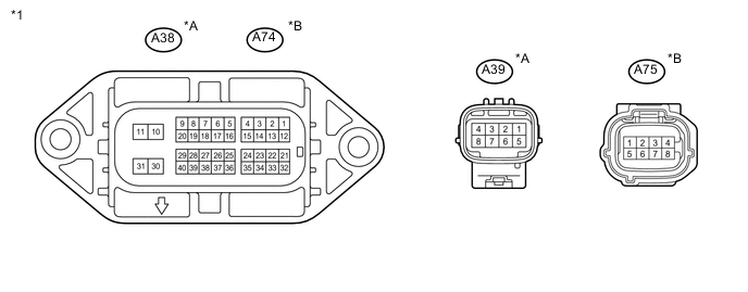
Text in Illustration *A for LHD *B for RHD *1 Inverter with Converter Assembly - - Tech Tips
Since the inverter with converter assembly uses waterproof connectors, the voltage and waveform cannot be inspected directly. Standard voltage readings and waveforms are indicated for reference only.
Inverter with converter assembly (for LHD) Terminal No.
(Symbol)
Wiring Color Terminal Description Condition Standard Condition A38-2 (MTH-) - A38-30 (GND1) W - W-B Communication signal from MG ECU to power management control ECU Power switch on (IG) Pulse generation
(Waveform 3)
A38-3 (MTH+) - A38-30 (GND1) B - W-B Communication signal from MG ECU to power management control ECU Power switch on (IG) Pulse generation
(Waveform 3)
A38-10 (+B) - A38-30 (GND1) L - W-B MG ECU power source Power switch on (IG) 11 to 14 V A38-11 (+B2) - A38-30 (GND1) L - W-B MG ECU power source Power switch on (IG) 11 to 14 V A38-13 (CLK-) - A38-30 (GND1) W - W-B MG ECU communication clock signal Power switch on (IG) Pulse generation
(Waveform 2)
A38-14 (CLK+) - A38-30 (GND1) B - W-B MG ECU communication clock signal Power switch on (IG) Pulse generation
(Waveform 2)
A38-16 (GI) - A38-30 (GND1) W - W-B Camshaft position sensor signal Power switch on (READY), with engine running Pulse generation
(Waveform 1)
A38-17 (GCS) - A38-6 (GCSG) R - W Generator resolver signal Generator resolver running Pulse generation
(Waveform 6)
A38-18 (GSN) - A38-7 (GSNG) Y - G Generator resolver signal Generator resolver running Pulse generation
(Waveform 6)
A38-20 (GRF) - A38-9 (GRFG) L - B Generator resolver signal Generator resolver running Pulse generation
(Waveform 6)
A38-22 (HTM-) - A38-30 (GND1) W - W-B Communication signal from power management control ECU to MG ECU Power switch on (IG) Pulse generation
(Waveform 4)
A38-23 (HTM+) - A38-30 (GND1) B - W-B Communication signal from power management control ECU to MG ECU Power switch on (IG) Pulse generation
(Waveform 4)
A38-24 (ILKO) - A38-30 (GND1) B - W-B Interlock switch signal Power switch on (IG), connector cover assembly, inverter terminal cover, No. 4 floor wire (air conditioning harness) and service plug grip installed correctly Below 1 V Power switch on (IG), connector cover assembly, inverter terminal cover, No. 4 floor wire (air conditioning harness) or service plug grip not installed 11 to 14 V A38-25 (HSDN) - A38-30 (GND1) B - W-B MG shutdown signal Power switch on (READY) 0 to 1 V A38-33 (REQ-) - A38-30 (GND1) W - W-B MG ECU communication request signal Power switch on (IG) Pulse generation
(Waveform 5)
A38-34 (REQ+) - A38-30 (GND1) B - W-B MG ECU communication request signal Power switch on (IG) Pulse generation
(Waveform 5)
A38-35 (ILKI) - A38-30 (GND1) L - W-B Interlock switch signal Power switch on (IG), connector cover assembly, inverter terminal cover, No. 4 floor wire (air conditioning harness) and service plug grip installed correctly Below 1 V Power switch on (IG), connector cover assembly, inverter terminal cover, No. 4 floor wire (air conditioning harness) or service plug grip not installed 11 to 14 V A38-38 (MCS) - A38-27 (MCSG) R - W Motor resolver signal Motor resolver running Pulse generation
(Waveform 7)
A38-39 (MSN) - A38-28 (MSNG) Y - G Motor resolver signal Motor resolver running Pulse generation
(Waveform 7)
A38-40 (MRF) - A38-29 (MRFG) L - B Motor resolver signal Motor resolver running Pulse generation
(Waveform 7)
A39-1 (IGCT) - A38-30 (GND1) R - W-B MG ECU power source Power switch on (IG) 11 to 14 V A39-2 (IDH) - A38-30 (GND1) W - W-B PTC heater prohibit signal Power switch on (IG) 4 to 6 V A39-3 (S) - A38-30 (GND1) G - W-B Auxiliary battery voltage monitor Power switch on (IG) 11 to 14 V A39-5 (NODD) - A38-30 (GND1) GR - W-B DC/DC operation DC/DC converter operating normally 5 to 7 V DC/DC converter not operating normally 2 to 4 V DC/DC converter operation prohibited 0.1 to 0.5 V A39-6 (VLO) - A38-30 (GND1) SB - W-B DC/DC operation monitor/voltage change signal Power switch on (IG) Pulse generation
(Waveform 8)
Inverter with converter assembly (for RHD) Terminal No.
(Symbol)
Wiring Color Terminal Description Condition Standard Condition A74-2 (MTH-) - A74-30 (GND1) W - W-B Communication signal from MG ECU to power management control ECU Power switch on (IG) Pulse generation
(Waveform 3)
A74-3 (MTH+) - A74-30 (GND1) B - W-B Communication signal from MG ECU to power management control ECU Power switch on (IG) Pulse generation
(Waveform 3)
A74-10 (+B) - A74-30 (GND1) L - W-B MG ECU power source Power switch on (IG) 11 to 14 V A74-11 (+B2) - A74-30 (GND1) L - W-B MG ECU power source Power switch on (IG) 11 to 14 V A74-13 (CLK-) - A74-30 (GND1) W - W-B MG ECU communication clock signal Power switch on (IG) Pulse generation
(Waveform 2)
A74-14 (CLK+) - A74-30 (GND1) B - W-B MG ECU communication clock signal Power switch on (IG) Pulse generation
(Waveform 2)
A74-16 (GI) - A74-30 (GND1) W - W-B Camshaft position sensor signal Power switch on (READY), with engine running Pulse generation
(Waveform 1)
A74-17 (GCS) - A74-6 (GCSG) R - W Generator resolver signal Generator resolver running Pulse generation
(Waveform 6)
A74-18 (GSN) - A74-7 (GSNG) Y - G Generator resolver signal Generator resolver running Pulse generation
(Waveform 6)
A74-20 (GRF) - A74-9 (GRFG) L - B Generator resolver signal Generator resolver running Pulse generation
(Waveform 6)
A74-22 (HTM-) - A74-30 (GND1) W - W-B Communication signal from power management control ECU to MG ECU Power switch on (IG) Pulse generation
(Waveform 4)
A74-23 (HTM+) - A74-30 (GND1) B - W-B Communication signal from power management control ECU to MG ECU Power switch on (IG) Pulse generation
(Waveform 4)
A74-24 (ILKO) - A74-30 (GND1) B - W-B Interlock switch signal Power switch on (IG), connector cover assembly, inverter terminal cover, air conditioning harness and service plug grip installed correctly Below 1 V Power switch on (IG), connector cover assembly, inverter terminal cover, air conditioning harness or service plug grip not installed 11 to 14 V A74-25 (HSDN) - A74-30 (GND1) B - W-B MG shutdown signal Power switch on (READY) 0 to 1 V A74-33 (REQ-) - A74-30 (GND1) W - W-B MG ECU communication request signal Power switch on (IG) Pulse generation
(Waveform 5)
A74-34 (REQ+) - A74-30 (GND1) B - W-B MG ECU communication request signal Power switch on (IG) Pulse generation
(Waveform 5)
A74-35 (ILKI) - A74-30 (GND1) L - W-B Interlock switch signal Power switch on (IG), connector cover assembly, inverter terminal cover, air conditioning harness and service plug grip installed correctly Below 1 V Power switch on (IG), connector cover assembly, inverter terminal cover, air conditioning harness or service plug grip not installed 11 to 14 V A74-38 (MCS) - A74-27 (MCSG) R - W Motor resolver signal Motor resolver running Pulse generation
(Waveform 7)
A74-39 (MSN) - A74-28 (MSNG) Y - G Motor resolver signal Motor resolver running Pulse generation
(Waveform 7)
A74-40 (MRF) - A74-29 (MRFG) L - B Motor resolver signal Motor resolver running Pulse generation
(Waveform 7)
A75-1 (IGCT) - A74-30 (GND1) R - W-B MG ECU power source Power switch on (IG) 11 to 14 V A75-2 (IDH) - A74-30 (GND1) W - W-B PTC heater prohibit signal Power switch on (IG) 4 to 6 V A75-3 (S) - A74-30 (GND1) G - W-B Auxiliary battery voltage monitor Power switch on (IG) 11 to 14 V A75-5 (NODD) - A74-30 (GND1) GR - W-B DC/DC operation DC/DC converter operating normally 5 to 7 V DC/DC converter not operating normally 2 to 4 V DC/DC converter operation prohibited 0.1 to 0.5 V A75-6 (VLO) - A74-30 (GND1) SB - W-B DC/DC operation monitor/voltage change signal Power switch on (IG) Pulse generation
(Waveform 8)
Note
Do not measure the voltage or waveform directly at the sealed side of the inverter with converter assembly connector. Doing so may damage the connector because the connector is waterproof.
-
-
Oscilloscope waveforms
Tech Tips
Oscilloscope waveform samples are provided here for informational purposes. Noise and fluttering waveforms have been omitted.
-
Waveform 1 (Camshaft position sensor signal)
for LHD Item Content Terminal A38-16 (GI) - A38-30 (GND1) Equipment Setting 5 V/DIV., 20 ms./DIV. Condition Power switch on (READY), with engine running for RHD Item Content Terminal A74-16 (GI) - A74-30 (GND1) Equipment Setting 5 V/DIV., 20 ms./DIV. Condition Power switch on (READY), with engine running Tech Tips
The pulse cycle becomes shorter as the engine speed increases.
-
Waveform 2 (MG ECU communication clock signal)
for LHD Item Content Terminal CH1: A38-14 (CLK+) - A38-30 (GND1)
CH2: A38-13 (CLK-) - A38-30 (GND1)
Equipment Setting 1 V/DIV., 1 μs./DIV. Condition Power switch on (IG) for RHD Item Content Terminal CH1: A74-14 (CLK+) - A74-30 (GND1)
CH2: A74-13 (CLK-) - A74-30 (GND1)
Equipment Setting 1 V/DIV., 1 μs./DIV. Condition Power switch on (IG) -
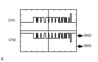
Waveform 3 (communication signal from MG ECU to power management control ECU)
for LHD Item Content Terminal CH1: A38-3 (MTH+) - A38-30 (GND1)
CH2: A38-2 (MTH-) - A38-30 (GND1)
Equipment Setting 1 V/DIV., 200 μs./DIV. Condition Power switch on (IG) for RHD Item Content Terminal CH1: A74-3 (MTH+) - A74-30 (GND1)
CH2: A74-2 (MTH-) - A74-30 (GND1)
Equipment Setting 1 V/DIV., 200 μs./DIV. Condition Power switch on (IG) Tech Tips
The waveform will vary depending on the content of the digital communication (digital signal).
-
Waveform 4 (communication signal from power management control ECU to MG ECU)
for LHD Item Content Terminal CH1: A38-23 (HTM+) - A38-30 (GND1)
CH2: A38-22 (HTM-) - A38-30 (GND1)
Equipment Setting 1 V/DIV., 200 μs./DIV. Condition Power switch on (IG) for RHD Item Content Terminal CH1: A74-23 (HTM+) - A74-30 (GND1)
CH2: A74-22 (HTM-) - A74-30 (GND1)
Equipment Setting 1 V/DIV., 200 μs./DIV. Condition Power switch on (IG) Tech Tips
The waveform will vary depending on the content of the digital communication (digital signal).
-
Waveform 5 (MG ECU communication request signal)
for LHD Item Content Terminal CH1: A38-34 (REQ+) - A38-30 (GND1)
CH2: A38-33 (REQ-) - A38-30 (GND1)
Equipment Setting 1 V/DIV., 1 ms./DIV. Condition Power switch on (IG) for RHD Item Content Terminal CH1: A74-34 (REQ+) - A74-30 (GND1)
CH2: A74-33 (REQ-) - A74-30 (GND1)
Equipment Setting 1 V/DIV., 1 ms./DIV. Condition Power switch on (IG) -
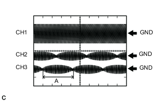
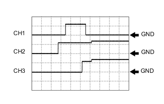
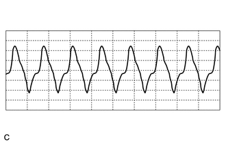
Waveform 6 (generator resolver signal)
for LHD Item Content Terminal CH1: A38-20 (GRF) - A38-9 (GRFG)
CH2: A38-18 (GSN) - A38-7 (GSNG)
CH3: A38-17 (GCS) - A38-6 (GCSG)
Equipment Setting CH1: 10 V/DIV., 1 ms./DIV.
CH2, 3: 5 V/DIV., 1 ms./DIV.
Condition Generator resolver running for RHD Item Content Terminal CH1: A74-20 (GRF) - A74-9 (GRFG)
CH2: A74-18 (GSN) - A74-7 (GSNG)
CH3: A74-17 (GCS) - A74-6 (GCSG)
Equipment Setting CH1: 10 V/DIV., 1 ms./DIV.
CH2, 3: 5 V/DIV., 1 ms./DIV.
Condition Generator resolver running Tech Tips
Pulse cycle A becomes shorter as the rotor speed increases.
-
Waveform 7 (motor resolver signal)
for LHD Item Content Terminal CH1: A38-40 (MRF) - A38-29 (MRFG)
CH2: A38-39 (MSN) - A38-28 (MSNG)
CH3: A38-38 (MCS) - A38-27 (MCSG)
Equipment Setting CH1: 10 V/DIV., 1 ms./DIV.
CH2, 3: 5 V/DIV., 1 ms./DIV.
Condition Motor resolver running for RHD Item Content Terminal CH1: A74-40 (MRF) - A74-29 (MRFG)
CH2: A74-39 (MSN) - A74-28 (MSNG)
CH3: A74-38 (MCS) - A74-27 (MCSG)
Equipment Setting CH1: 10 V/DIV., 1 ms./DIV.
CH2, 3: 5 V/DIV., 1 ms./DIV.
Condition Motor resolver running Tech Tips
Pulse cycle A becomes shorter as the rotor speed increases.
-
Waveform 8 (DC/DC operation monitor/voltage change signal)
for LHD Item Content Terminal A39-6 (VLO) - A38-30 (GND1) Equipment Setting 5 V/DIV., 50 ms./DIV. Condition Power switch on (IG) for RHD Item Content Terminal A75-6 (VLO) - A74-30 (GND1) Equipment Setting 5 V/DIV., 50 ms./DIV. Condition Power switch on (IG) Tech Tips
The cycle will vary depending on the specified voltage of the hybrid vehicle converter.
-