HYBRID CONTROL SYSTEM SYSTEM DESCRIPTION
-
OPERATION
-
Operation of Hybrid Vehicle
-
The hybrid system uses motive force provided by the engine and MG2, and it uses MG1 primarily as a generator. The system optimally combines these forces in accordance with various driving conditions.
-
The power management control ECU constantly monitors the State Of Charge (SOC) of the HV battery, the HV battery temperature, the engine coolant temperature and the electrical load condition. If any one of the monitoring items fails to satisfy requirements when the READY indicator light is on and the shift lever is in P, R, D or S, or if the vehicle is driven in reverse, the power management control ECU demands an engine start to drive MG1 in order to charge the HV battery.
-
The hybrid system drives the vehicle by optimally combining the operation of the engine, MG1 and MG2 in accordance with the driving conditions listed in the table below:
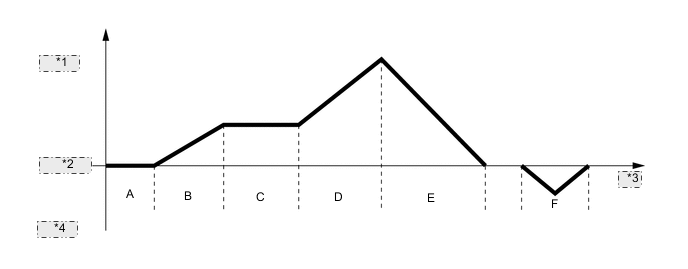
*1 Forward *2 Vehicle Speed *3 Time *4 Reverse Driving Condition A READY-ON State B Starting Off C Constant-speed Cruising D During Full Throttle Acceleration E During Deceleration F During Reverse Driving
-
-
Driving Condition A: READY-ON State
-
Even if the driver turns the power switch on (READY), sometimes the engine will not start. If this happens, the engine, MG1 and MG2 remain stopped. The engine will only start if conditions such as engine coolant temperature, SOC of the HV battery, HV battery temperature and electrical load require an engine start.
-
After driving, if the driver stops the vehicle and moves the shift lever to P, the power management control ECU will continue to operate the engine. The engine will continue to operate until SOC of the HV battery, engine coolant temperature, HV battery temperature and/or electrical load conditions reach a specified level.
-
If any of the items monitored by the power management control ECU indicates the need for an engine start when the READY indicator light is on and the shift lever is in P, the power management control ECU will activate MG1 to start the engine.
-
While the engine is cranking, to prevent the reactive force of the sun gear of MG1 from rotating the ring gear and driving the drive wheels, current is also applied to MG2 in order to prevent MG2 from rotating. This function is called "reactive control".
Text in Illustration *1 Engine *2 Hybrid Vehicle Transmission Assembly *3 Power Split Planetary Gear *4 2-stage Motor Speed Reduction Planetary Gear *5 MG1 *6 MG2 *7 Inverter with Converter Assembly *8 Differential *9 HV Battery - - *a Driven *b Drive *c Discharge - - 
Power Transmission 
Mechanical Power Path 
Electrical Power Path (DC) 
Electrical Power Path (AC) -
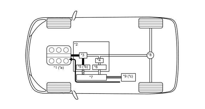
If the SOC of the HV battery is low, it is charged by MG1 which is driven by the engine.

Text in Illustration *1 Engine *2 Hybrid Vehicle Transmission Assembly *3 Power Split Planetary Gear *4 2-stage Motor Speed Reduction Planetary Gear *5 MG1 *6 MG2 *7 Inverter with Converter Assembly *8 Differential *9 HV Battery - - *a Drive *b Driven - Generates Electricity *c Charged by MG1 - - Power Transmission Mechanical Power Path Electrical Power Path (DC) Electrical Power Path (AC)
-
-
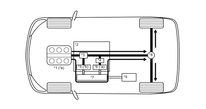
Driving Condition B: Starting Off
-
When the vehicle is started off, the vehicle operates powered by MG2.
Text in Illustration *1 Engine *2 Hybrid Vehicle Transmission Assembly *3 Power Split Planetary Gear *4 2-stage Motor Speed Reduction Planetary Gear *5 MG1 *6 MG2 *7 Inverter with Converter Assembly *8 Differential *9 HV Battery - - *a Stopped *b Rotates Freely *c Drive *d Discharge Power Transmission Mechanical Power Path Electrical Power Path (DC) Electrical Power Path (AC) -
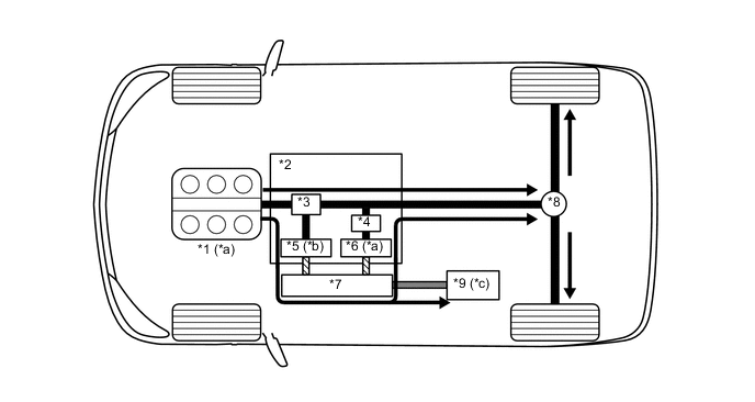
If the SOC of the HV battery is low, it is charged by MG1 which is driven by the engine. The electricity from MG1 is also used to drive MG2.
Text in Illustration *1 Engine *2 Hybrid Vehicle Transmission Assembly *3 Power Split Planetary Gear *4 2-stage Motor Speed Reduction Planetary Gear *5 MG1 *6 MG2 *7 Inverter with Converter Assembly *8 Differential *9 HV Battery - - *a Drive *b Driven - Generates Electricity *c Charged by MG1 - - Power Transmission Mechanical Power Path Electrical Power Path (DC) Electrical Power Path (AC)
-
-
Driving Condition C: During Low Load and Constant-speed Cruising
-
When the vehicle is running under constant-speed cruising conditions, the engine will be operated in its most efficient range to power the vehicle.
-
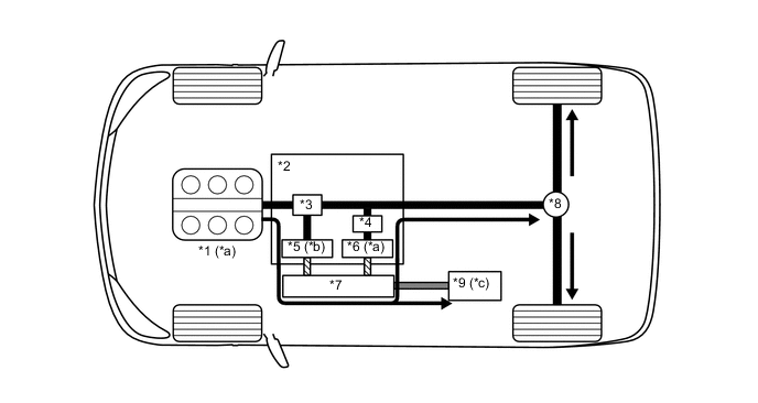
The motive force from the engine is split into two in the power split planetary gear. One portion of the motive force is used to drive the wheels directly and the other is used to generate electricity using MG1.
-
The electricity from MG1 is used to drive MG2. This supports the directly transmitted engine motive force, contributing to fuel efficiency.
Text in Illustration *1 Engine *2 Hybrid Vehicle Transmission Assembly *3 Power Split Planetary Gear *4 2-stage Motor Speed Reduction Planetary Gear *5 MG1 *6 MG2 *7 Inverter with Converter Assembly *8 Differential *9 HV Battery - - *a Drive *b Driven - Generates Electricity Power Transmission Mechanical Power Path Electrical Power Path (AC) - - -
If the SOC of the HV battery is low, more engine power is provided to increase the generation of electricity via MG1. This charges the HV battery.
Text in Illustration *1 Engine *2 Hybrid Vehicle Transmission Assembly *3 Power Split Planetary Gear *4 2-stage Motor Speed Reduction Planetary Gear *5 MG1 *6 MG2 *7 Inverter with Converter Assembly *8 Differential *9 HV Battery - - *a Drive *b Driven - Generates Electricity *c Charged by MG1 - - Power Transmission Mechanical Power Path Electrical Power Path (DC) Electrical Power Path (AC)
-
-
Driving Condition D: During Full Throttle Acceleration
-
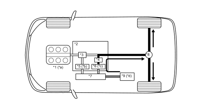
When the vehicle driving condition changes from low load cruising to full throttle acceleration, the system supplements the motive force of MG2 with electrical power from the HV battery.
Text in Illustration *1 Engine *2 Hybrid Vehicle Transmission Assembly *3 Power Split Planetary Gear *4 2-stage Motor Speed Reduction Planetary Gear *5 MG1 *6 MG2 *7 Inverter with Converter Assembly *8 Differential *9 HV Battery - - *a Drive *b Driven - Generates Electricity *c Discharge - - Power Transmission Mechanical Power Path Electrical Power Path (DC) Electrical Power Path (AC)
-
-
Driving Condition E: During Deceleration
-
While the vehicle is being driven with the shift lever in D and it decelerates, the engine turns off and the engine motive force output to the wheels will be zero. At this time, the wheels drive MG2, causing MG2 to operate as a generator and charge the HV battery. While MG2 is operating as a generator, it creates a resistance to rotation at the wheels, producing a braking effect.
-
If the vehicle decelerates at a higher speed, the engine (crankshaft) will not stop turning. The engine will maintain a predetermined speed in order to protect the planetary gear unit. This operation is not shown in the following diagrams.

Text in Illustration *1 Engine *2 Hybrid Vehicle Transmission Assembly *3 Power Split Planetary Gear *4 2-stage Motor Speed Reduction Planetary Gear *5 MG1 *6 MG2 *7 Inverter with Converter Assembly *8 Differential *9 HV Battery - - *a Stopped *b Rotates Freely *c Driven - Generates Electricity *d Charged by MG2 Power Transmission Mechanical Power Path Electrical Power Path (DC) Electrical Power Path (AC)
-
-
Driving Condition F: Driving in Reverse
-
While the vehicle is being driven in reverse, its power is delivered by MG2. At this time, MG2 is spinning in the opposite (-) direction of forward travel, the engine can remain stopped, and MG1 is spinning in the (+) direction without generating electricity.
-
While driving in reverse, when any of the conditions monitored by the power management control ECU, such as the SOC of the HV battery, HV battery temperature, engine coolant temperature and electrical load condition, reach a specified level, MG1 will be used to start the engine. The following illustration represents an example when the engine is not running:
Text in Illustration *1 Engine *2 Hybrid Vehicle Transmission Assembly *3 Power Split Planetary Gear *4 2-stage Motor Speed Reduction Planetary Gear *5 MG1 *6 MG2 *7 Inverter with Converter Assembly *8 Differential *9 HV Battery - - *a Stopped *b Rotates Freely *c Drive *d Discharge Power Transmission Mechanical Power Path Electrical Power Path (DC) Electrical Power Path (AC)
-
-
-
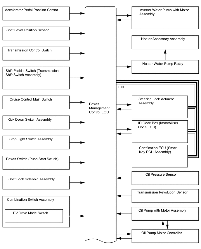
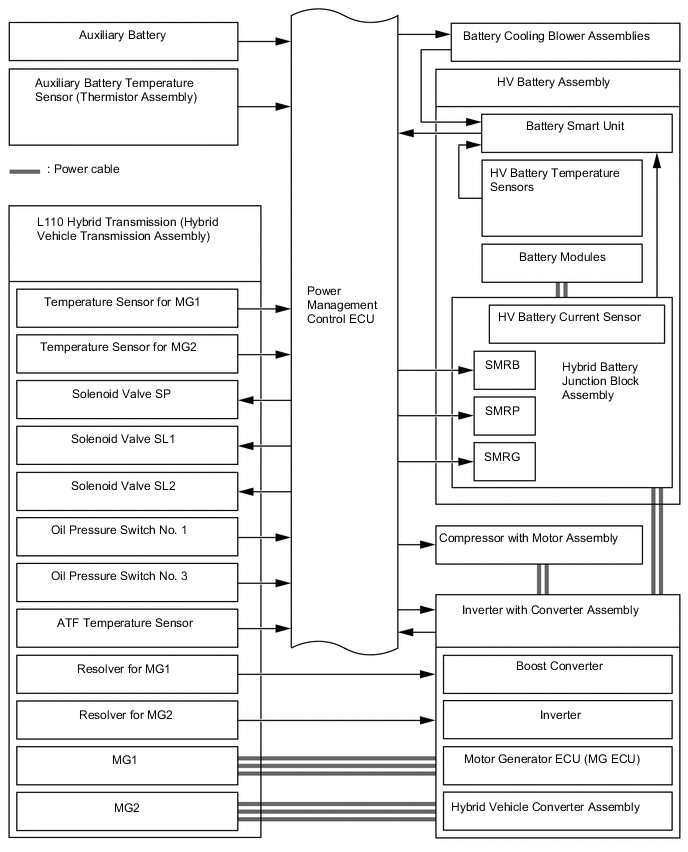
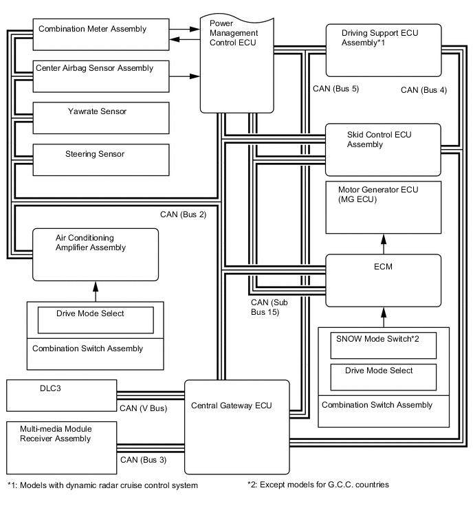
SYSTEM DIAGRAM
-
FUNCTION OF MAIN COMPONENTS
Component Function Hybrid Vehicle Transmission Assembly MG1
-
Driven by the engine, generates high-voltage electricity in order to operate MG2 and/or charge the HV battery. Also, it functions as a starter to start the engine.
-
MG1 is operated so that the gear ratio of the power split planetary gear unit will optimally suit the driving conditions of the vehicle.
MG2
-
Driven by electrical power from MG1 and/or the HV battery, and generates motive force for the rear wheels.
-
During braking, or when the accelerator pedal is not depressed, it generates electricity to recharge the HV battery (regenerative braking).
Resolvers
-
MG1 and MG2 are each equipped with a resolver.
-
Send the rotational speed and direction of the motor generators to the MG ECU.
Temperature Sensors for Motor Generator
-
MG1 and MG2 are each equipped with a temperature sensor.
-
Measure the temperature of MG1 and MG2.
Compound Gear Unit Power Split Planetary Gear Distributes the engine motive force as appropriate to directly drive the vehicle as well as MG1. 2-stage Motor Speed Reduction Planetary Gear Reduces the rotational speed of MG2 in accordance with the characteristics of the planetary gear, in order to increase torque. Furthermore, it shifts the transmission in 2 stages in accordance with the conditions of the vehicle. Valve Body Unit Solenoid Valves (SL1/SL2) Switches low-speed range and high-speed range. Solenoid Valve (SP) Controls line pressure. Oil Pressure Switches (PB1/PB3) Detect the oil pressure in the oil pressure control circuit. Transmission Fluid Temperature Sensor Detects the transmission fluid temperature. Mechanical Oil Pump Driven by engine power, supplies oil pressure to the valve body unit and lubricates the planetary gear. Oil Pressure Sensor Detects the oil pressure in the oil pressure control circuit. Transmission Revolution Sensor (SP2) Detects the output speed of the transmission. Shift Lever Position Sensor Converts the shift lever position into electrical signals and outputs them to the power management control ECU. Oil Pump with Motor Assembly Supplies oil pressure to the valve body unit and lubricates the planetary gear mainly when the engine is stopped. Oil Pump Motor Controller Drives the oil pump with motor assembly in accordance with a signal from the power management control ECU to variably regulate the ATF discharge amount. Inverter with Converter Assembly Inverter A device that converts high-voltage DC (HV battery) into AC (MG1 and MG2) and vice versa (converts AC into DC). Boost Converter Boosts the voltage of the HV battery from DC 288 V to a maximum of DC 650 V and vice versa (drops DC 650 V to DC 288 V). DC/DC Converter Assembly Drops the HV battery voltage of DC 288 V to approximately DC 14 V in order to supply electricity to body electrical components, as well as to recharge the auxiliary battery. Motor Generator ECU (MG ECU) Controls the inverter and boost converter in accordance with signals received from the power management control ECU, thus operating MG1 or MG2 as either a generator or motor. Inverter Current Sensors
-
MG1 and MG2 are each provided with 2 current sensors.
-
Measure the current of the MG1 and MG2.
Inverter Temperature Sensors
-
Provided for the boost converter, Intelligent Power Module (IPM) for MG1 and MG2, and inverter coolant.
-
Measure the temperature of boost converter, IPM for MG1 and MG2, and inverter coolant.
Atmospheric Pressure Sensor Detects the atmospheric pressure. Inverter Radiator Cools inverter coolant. Inverter Water Pump with Motor Assembly Controlled in 3 stages by the power management control ECU in accordance with inverter coolant temperatures in order to cool the inverter coolant. Interlock Switches
- Inverter Terminal Cover
- Connector Cover Assembly
- Power Cable
- Service Plug Grip
Verify that the inverter terminal cover, connector cover assembly, service plug grip and power cable are installed. Power Cable Connects the HV battery with inverter with converter assembly, the inverter with converter assembly with MG1 and MG2, and the inverter with converter with the compressor with motor assembly. HV Battery Assembly HV Battery (Battery Modules)
-
Supplies electrical power to MG1, MG2, compressor with motor assembly in accordance with the driving conditions of the vehicle.
-
Charged by MG1 and MG2 in accordance with the State Of Charge (SOC) of the HV battery and the driving conditions of the vehicle.
-
Has a nominal (approximate) voltage of DC 288 V (actual voltage will vary depending on various conditions such as temperature, charge or discharge).
Battery Smart Unit
-
Monitors frequency from the battery cooling blower assembly and conditions of the HV battery such as voltage, temperature and current, and transmits this information to the power management control ECU.
-
Monitors the high voltage system for breakdown of the electrical insulation.
Hybrid Battery Junction Block Assembly System Main Relays (SMRs) Connect and disconnect the high-voltage power circuit between the HV battery and inverter with converter assembly. The power management control ECU controls the SMRs by turning them on or off as appropriate. HV Battery Current Sensor Measures the current of the HV battery. HV Battery Temperature Sensors Detect temperatures in the parts of the HV battery. HV Battery Intake Air Temperature Sensor Detects the intake air temperature from the battery cooling blower assembly. Battery Cooling Blower Assemblies Operate under the control of the power management control ECU in order to cool the HV battery. Service Plug Grip Shuts off the high-voltage circuit of the HV battery when this plug is removed for vehicle inspection or maintenance. Auxiliary Battery When the power switch is on, the auxiliary battery supplies the power to the electrical equipment and ECUs. Auxiliary Battery Temperature Sensor (Thermistor Assembly) Measures the temperature of the auxiliary battery for auxiliary battery protection. Compressor with Motor Assembly Driven at a speed calculated by the air conditioning amplifier assembly, receives drive requests from the power management control ECU and takes in, compresses and discharges refrigerant. Heater Accessory Assembly Controlled via the power management control ECU in accordance with signals from the air conditioning amplifier assembly, and circulates coolant to ensure heater source stability during idling stop control. Speed Sensors Detects the wheel speed of each of the 4 wheels. Steering Sensor Detects the direction and angle of the steering wheel. Yaw Rate Sensor
-
Detects the vehicle's longitudinal and lateral acceleration.
-
Detects the vehicle's yaw rate.
Accelerator Pedal Sensor Assembly Converts the accelerator pedal position into an electrical signal and outputs it to the power management control ECU. Kick Down Switch Assembly Detects that the accelerator pedal is almost fully depressed. Brake Pedal Stroke Sensor Assembly Directly detects the extent of the brake pedal stroke operated by the driver. Stop Light Switch Assembly Detects the brake pedal depressing signal. Cruise Control Main Switch Turns the cruise control system and dynamic radar cruise control system on and off, and conducts various operations including vehicle speed setting, acceleration, deceleration and control cancellation. Shift Paddle Switch (Transmission Shift Switch Assembly) Detects the driver's shift-up and shift-down operations. Transmission Control Switch (Transmission Floor Shift Assembly)
-
Detects that the shift lever is in S.
-
Detects the driver's shift-up and shift-down operations when the shift lever is in S.
Combination Switch Assembly EV Mode Switch Outputs the EV mode switch signal to the power management control ECU when operated by the driver. Drive Mode Select
-
Outputs the NORMAL mode signal to the power management control ECU via the ECM when operated by the driver.
-
Outputs the ECO mode signal to the power management control ECU via the air conditioning amplifier assembly when operated by the driver.
-
Outputs the SPORT mode signal to the power management control ECU via the ECM when operated by the driver.
SNOW Mode Switch*1 Outputs the SNOW mode switch signal to the power management control ECU via the ECM when operated by the driver. Power Management Control ECU
-
Performs comprehensive control of the hybrid system. This includes the electric continuously variable transmission and HV battery.
-
Information from various sensors as well as from ECUs (ECM, battery voltage sensor, MG ECU and skid control ECU) is received, and the required torque and output power are calculated based on this. The power management control ECU sends the calculated result to the ECM, MG ECU and skid control ECU.
-
Monitors the SOC of the HV battery.
-
Controls the oil pump with motor assembly.
-
Controls the hybrid vehicle converter assembly.
-
Controls the inverter water pump with motor assembly.
-
Controls the battery cooling blower assemblies.
ECM
-
Performs control of the engine in accordance with the target engine speed and required engine motive force received from the power management control ECU.
-
Transmits the operating condition signals of the engine to the power management control ECU.
Skid Control ECU Assembly
-
During braking, it calculates the regenerative braking force that is required and transmits it to the power management control ECU.
-
Calculates the motive force that is required during the operation of TRC or VSC and transmits it to the power management control ECU.
Air Conditioning Amplifier Assembly Transmits various air conditioning state signals to the power management control ECU. Center Airbag Sensor Assembly During a collision, it transmits the airbag deployment signal to the power management control ECU. Driving Support ECU Assembly*2 Sends the information about the operation conditions of the dynamic radar cruise control system to the power management control ECU. Multi-media Module Receiver Assembly
-
Displays hybrid system output and charging of the hybrid battery on the energy monitor in the display.
-
Displays the drive mode on the display.
Combination Meter Assembly Hybrid System Indicator Indicates the hybrid system output and charging of the hybrid battery to inform the driver. READY Indicator Light Informs the driver that the vehicle is ready to drive. EV Mode Indicator Light Informs the driver that the EV mode is entered. MIL Turns on when there is a malfunction in the engine control system. Charge Warning Light Turns on when there is a malfunction in the auxiliary battery charging system. Master Warning Light In this context, the primary function of this warning light is to inform the driver of a malfunction in the hybrid system or when the SOC of the HV battery is too low. The light illuminates simultaneously with the sounding of a warning buzzer. Multi-information Display
-
Displays the shift lever position.
-
Displays the shift position.
-
Displays the energy flow.
-
Displays the EV mode.
-
Displays the drive mode.
-
Displays the SNOW mode.
-
Displays messages to inform the driver when a malfunction occurs.
-
Shows system status and appropriate operations to be performed.
Meter Panel Illumination Illuminates in blue or red in response to drive mode. Also, the brightness level changes when illuminated in blue in accordance with driving conditions.
-
*1: w/ SNOW Mode Switch
-
*2: w/ Dynamic Radar Cruise Control System
-