WATER PUMP WITH MOTOR INSTALLATION
PROCEDURE
-
INSTALL INVERTER WATER PUMP WITH MOTOR ASSEMBLY
-
Install the inverter water pump with motor assembly to the HV water pump bracket sub-assembly with the 3 bolts.
- Torque:
- 6.1 N*m { 62 kgf*cm, 54 in.*lbf }
Note
Do not hold the inverter water pump with motor assembly by the connector terminals when removing or installing it.
Tech Tips
Temporarily install the 3 bolts, and then fully tighten 1 of the bolts.
-
-
INSTALL HV WATER PUMP BRACKET SUB-ASSEMBLY
-
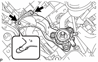
Text in Illustration *a Claw Install the HV water pump bracket sub-assembly with 2 bolts.
- Torque:
- 13 N*m { 127 kgf*cm, 9 ft.*lbf }
Note
Attach the claw of the HV water pump bracket sub-assembly to the hole in the body as shown in the illustration.
-
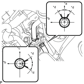
Text in Illustration *a Upper *b Front *c RH Side *d 30° Connect the hybrid water pump inlet hose and No. 1 hybrid water pump outlet hose to the inverter water pump with motor assembly, and slide the 2 clamps to secure the hose.
Note
-
Make sure that the clamps are positioned as shown in the illustration.
-
Do not remove the pieces of cloth or plastic bags from the pipe and disconnected hose until installation.
-
-
Attach the 2 clamps and connect the inverter water pump connector.
-
Attach the inverter cooling hose clamp to the HV water pump bracket sub-assembly.
-
-
ADD COOLANT (for Inverter)
-
INSPECT FOR COOLANT LEAK (for Inverter)
-
INSTALL AIR CLEANER CASE SUB-ASSEMBLY
-
INSTALL AIR CLEANER FILTER ELEMENT SUB-ASSEMBLY
-
INSTALL AIR CLEANER CAP WITH NO. 2 AIR CLEANER HOSE
-
INSTALL NO. 1 AIR CLEANER INLET
-
INSTALL COOL AIR INTAKE DUCT SEAL
-
INSTALL ENGINE ROOM SIDE COVER
-
INSTALL ENGINE UNDER COVER