HYBRID CONTROL SYSTEM Drive Start Control System
DESCRIPTION
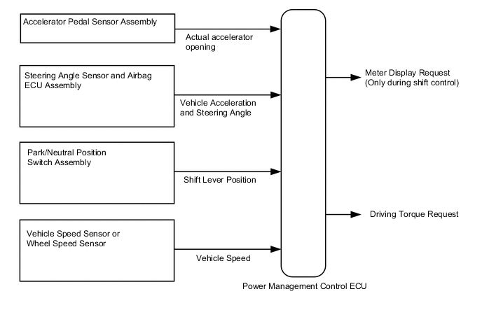
The drive start control is controlled by the power management control ECU.
If the power management control ECU determines that the shift lever and accelerator pedal are operated abnormally, driving torque is restricted and, when necessary, a warning is displayed on the combination meter assembly.
CAUTION / NOTICE / HINT
Tech Tips
Even if the accelerator pedal position is maintained, the engine output may increase when driving uphill and decrease when driving downhill. This is due to the drive start control controlling the driving torque, and is not a malfunction.
PROCEDURE
-
SYMPTOM CONFIRMATION
-
Interview the customer to confirm the problem.
Result Result Proceed to Hunting A Hesitation/poor acceleration B
B 
PAST ACTIVATION CONFIRMATION Click here
A 
-
-
PAST ACTIVATION CONFIRMATION
-
Check if the customer operated the vehicle in a way that would cause the drive start control to operate.
Tech Tips
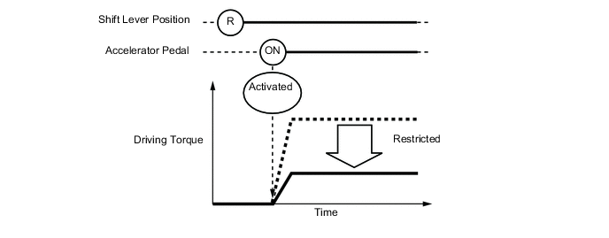
Drive Start Control Activation ConditionsCondition 1 (Reverse control)
Activation conditions
-
The shift lever is in R.
-
The accelerator pedal is depressed.
Items Controlled
-
Driving torque is restricted.
Deactivation Conditions
-
The shift lever is moved to any position other than R.
-
The accelerator pedal is released.
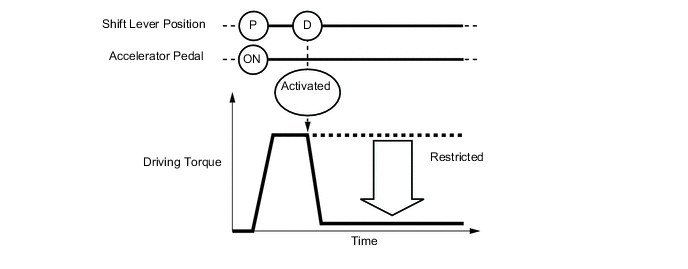
Condition 2 (Shift control a)
Activation conditions
-
The shift lever is moved from P to any forward position (D or S) or R.
-
The accelerator pedal is open by approximately 1/5 or more.
Items Controlled
-
Driving torque is restricted.
Deactivation Conditions
-
The shift lever is in P or N.
-
The accelerator pedal is released.
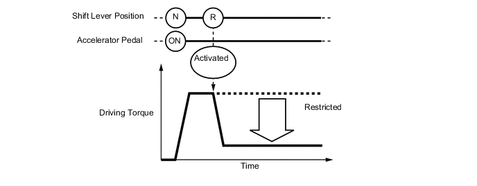
Condition 3 (Shift control b)
Activation conditions
-
The shift lever is moved from R to any forward position (D or S), any forward position (D or S) to R, or N to R.
-
The accelerator pedal is open by approximately 1/5 or more.
Items Controlled
-
Driving torque is restricted.
Deactivation Conditions
-
The shift lever is in P or N.
-
The accelerator pedal is released.
Tech Tips
During reverse control or shift control, driving torque is adjusted based on the road gradient and steering angle.
Result Result Proceed to Performed A Not performed B -
B 
SYSTEM NORMAL (GO TO PROBLEM SYMPTOM TABLE) Click here
A
-
-
CHECK DTC OUTPUT (HEALTH CHECK)
-
Connect the GTS to the DLC3.
-
Turn the power switch on (IG).
-
Enter the following menus: System Select / Health Check.
-
Check DTCs.
Result Result Proceed to No DTCs are output. A DTCs are output. B -
Turn the power switch off.
B
GO TO DTC CHART
A
-
-
READ VALUE USING GTS (FR, FL, RR, RL WHEEL SPEED)
-
Connect the GTS to the DLC3.
-
Turn the power switch on (READY).
-
Enter the following menus: Chassis / ABS/VSC/TRAC / Data List / FR Wheel Speed, FL Wheel Speed, RR Wheel Speed and RL Wheel Speed.
-
Read the value displayed on the GTS.
Tester Display Measurement Item/Range Normal Condition FR Wheel Speed Front wheel speed sensor RH /
Min.: 0 km/h (0 mph), Max.: 326 km/h (202 mph)
Vehicle stopped:
0 km/h (0 mph)
When driving at constant speed:
No large fluctuations
FL Wheel Speed Front wheel speed sensor LH / /
Min.: 0 km/h (0 mph), Max.: 326 km/h (202 mph)
RR Wheel Speed Rear wheel speed sensor RH /
Min.: 0 km/h (0 mph), Max.: 326 km/h (202 mph)
RL Wheel Speed Rear wheel speed sensor LH /
Min.: 0 km/h (0 mph), Max.: 326 km/h (202 mph)
Result Result Proceed to Displayed speed value does not fluctuate. A Displayed speed value fluctuates. B CAUTION:
Perform this road test only in an appropriate safe location, in accordance with all local laws.
Tech Tips
Data can be captured relatively easily by using the snapshot function in the Data List. Confirm the data after performing the drive test.
-
Turn the power switch off.
NG
INSPECT FRONT OR REAR SPEED SENSOR Click here
OK
-
-
READ VALUE USING GTS (VEHICLE SPD)
-
Connect the GTS to the DLC3.
-
Turn the power switch on (READY).
-
Enter the following menus: Powertrain / Hybrid Control / Data List / Vehicle Spd.
-
Read the value displayed on the GTS.
Tester Display Measurement Item/Range Normal Condition Vehicle Spd Vehicle speed/
Min.: 0 km/h (0 mph), Max.: 255 km/h (158 mph)
Vehicle stopped:
0 km/h (0 mph)
While driving at a constant speed:
No significant fluctuation
Result Result Proceed to Displayed speed value does not fluctuate. A Displayed speed value fluctuates. B CAUTION:
Perform this road test only in an appropriate safe location, in accordance with all local laws.
Tech Tips
Data can be captured relatively easily by using the snapshot function in the Data List. Confirm the data after performing the drive test.
-
Turn the power switch off.
NG
INSPECT ELECTRONICALLY CONTROLLED BRAKE SYSTEM (HOW TO PROCEED WITH TROUBLESHOOTING) Click here
OK
-
-
READ VALUE USING GTS (DECELERATION SENSOR)
-
Connect the GTS to the DLC3.
-
Turn the power switch on (IG).
-
Enter the following menus: Powertrain / Hybrid Control / Data List / Deceleration Sensor and Deceleration Sensor2.
-
Read the value displayed on the GTS.
Tester Display Condition Specified Condition Deceleration Sensor
Deceleration Sensor2
During deceleration Value changes with vehicle speed During acceleration Value changes with vehicle speed CAUTION:
When performing the confirmation driving pattern, obey all speed limits and traffic laws.
Tech Tips
Data can be captured relatively easily by using the snapshot function in the Data List. Confirm the data after performing the drive test.
-
Turn the power switch off.
NG
INSPECT YAW RATE SENSOR Click here
OK
-
-
READ VALUE USING GTS (STEERING ANGLE SENSOR)
-
Connect the GTS to the DLC3.
-
Turn the power switch on (READY).
-
Enter the following menus: Powertrain / Hybrid Control / Data List / Steering Angle Sensor.
-
Read the value displayed on the GTS.
Tester Display Measurement Item/Range Specified Condition Steering Angle Sensor Steering angle sensor
Min.: -3276.8 degrees, Max.: 3276.7 degrees
Turning left: Increases
Turning right: Decreases
Standard: Condition Specified Condition Steering wheel turned left Value increases with steering wheel operation Steering wheel turned right Value decreases with steering wheel operation Note
When performing the confirmation driving pattern, obey all speed limits and traffic laws.
Tech Tips
Data can be captured relatively easily by using the snapshot function in the Data List. Confirm the data after performing the drive test.
-
Turn the power switch off.
OK
SYSTEM NORMAL (GO TO PROBLEM SYMPTOM TABLE) Click here
NG
INSPECT STEERING ANGLE SENSOR Click here
-
-
PAST ACTIVATION CONFIRMATION
-
Check if the customer operated the vehicle in a way that would cause the drive start control to operate.
Tech Tips
Drive Start Control Activation ConditionsCondition 1 (Reverse control)
Activation conditions
-
The shift lever is in R.
-
The accelerator pedal is depressed.
Items Controlled
-
Driving torque is restricted.
Deactivation Conditions
-
The shift lever is moved to any position other than R.
-
The accelerator pedal is released.
Condition 2 (Shift control a)
Activation conditions
-
The shift lever is moved from P to any forward position (D, S or M) or R.
-
The accelerator pedal is open by approximately 1/5 or more.
Items Controlled
-
Driving torque is restricted.
Deactivation Conditions
-
The shift lever is in P or N.
-
The accelerator pedal is released.
Condition 3 (Shift control b)
Activation conditions
-
The shift lever is moved from R to any forward position (D, S or M), any forward position (D, S or M) to R, or N to R.
-
The accelerator pedal is open by approximately 1/5 or more.
Items Controlled
-
Driving torque is restricted.
Deactivation Conditions
-
The shift lever is in P or N.
-
The accelerator pedal is released.
Tech Tips
During reverse control or shift control, driving torque is adjusted based on the road gradient and steering angle.
Result Result Proceed to Not performed A Performed B Tech Tips
If the customer operated the vehicle in a way which caused the drive start control to operate, explain the operation of the system to the customer and that the operation is not a malfunction.
-
B
SYSTEM NORMAL
A
-
-
CHECK DTC OUTPUT (HEALTH CHECK)
-
Connect the GTS to the DLC3.
-
Turn the power switch on (IG).
-
Enter the following menus: System Select / Health Check.
-
Check DTCs.
Result Result Proceed to No DTCs are output. A DTCs are output. B -
Turn the power switch off.
B
GO TO DTC CHART
A
-
-
INSPECT PARK/NEUTRAL POSITION SWITCH ASSEMBLY
-
Inspect the park/neutral position switch assembly Click here.
B
REPLACE PARK/NEUTRAL POSITION SWITCH ASSEMBLY Click here
A
-
-
READ VALUE USING GTS (ACCEL PEDAL POS #1, ACCEL PEDAL POS #2)
-
Connect the GTS to the DLC3.
-
Turn the power switch on (IG).
-
Enter the following menus: Powertrain / Hybrid Control / Data List / Accel Pedal Pos #1, Accel Pedal Pos #2.
-
Read the value displayed on the GTS.
Tester Display Measurement Item/Range Normal Condition Accel Pedal Pos #1 Accelerator pedal position sensor No.1/
Min.: 0.0%, Max.: 100.0%
Accelerator pedal depressed:
Changes with accelerator pedal pressure
Accel Pedal Pos #2 Accelerator pedal position sensor No.2/
Min.: 0.0%, Max.: 100.0%
OK Condition Specified Condition Accelerator Pedal Released → Depressed Values smoothly change following accelerator pedal operation -
Turn the power switch off.
OK
SYSTEM NORMAL (GO TO PROBLEM SYMPTOM TABLE) Click here
B
REPLACE ACCELERATOR PEDAL SENSOR ASSEMBLY Click here
-