HYBRID CONTROL SYSTEM, Diagnostic DTC:P3004-131
| DTC Code | DTC Name |
|---|---|
| P3004-131 | High Voltage Power Resource |
DESCRIPTION
Refer to the description for DTC P0AE6-225 Click here.
The power management control ECU monitors the high-voltage wiring between the HV battery and the inverter with converter assembly and detects the following malfunction.
| DTC No. | DTC Detection Condition | Trouble Area |
|---|---|---|
| P3004-131 | Although an SMR on request was sent when the power switch is operated, the voltage after boosting did not increase. High-voltage circuit malfunctions between the HV battery and inverter with converter assembly. The EV electric battery fuse is blown, the service plug grip is removed, the system main resistor is blown, SMRP or SMRB remains open, or the high-voltage cable has an open circuit. (2 trip detection logic) |
|
| DTC No. | Data List |
|---|---|
| P3004-131 |
|
Use the following items as references when performing repairs.
-
Ready Signal
-
VL-Voltage before Boosting
-
Inter Lock Switch
-
SMRP Status
-
SMRB Status
-
SMRG Status
Data List
WIRING DIAGRAM
-
Refer to the wiring diagram for DTC P0AA6-526 Click here.
-
Refer to the wiring diagram for DTC P0AE6-225 Click here.
CAUTION / NOTICE / HINT
CAUTION:
-
Before inspecting the high-voltage system or disconnecting the low voltage connector of the inverter with converter assembly, take safety precautions such as wearing insulated gloves and removing the service plug grip to prevent electrical shocks. After removing the service plug grip, put it in your pocket to prevent other technicians from accidentally reconnecting it while you are working on the high-voltage system.
-
After removing the service plug grip, wait for at least 10 minutes before touching any of the high-voltage connectors or terminals. After waiting for 10 minutes, check the voltage at the terminals in the inspection point in the inverter with converter assembly. The voltage should be 0 V before beginning work Click here.
Tech Tips
Waiting for at least 10 minutes is required to discharge the high-voltage capacitor inside the inverter with converter assembly.
-
When disposing of an HV battery, make sure to return it through an authorized collection agent who is capable of handling it safely. If the HV battery is returned via the manufacturer specified route, it will be returned properly and in a safe manner by an authorized collection agent.
Note
After turning the power switch off, waiting time may be required before disconnecting the cable from the negative (-) auxiliary battery terminal. Therefore, make sure to read the disconnecting the cable from the negative (-) auxiliary battery terminal notices before proceeding with work Click here.
Tech Tips
After the repair, clear the DTCs, perform the following procedure and check that the same DTC (including pending DTC) is not output.
-
Turn the power switch off and wait for 30 seconds or more.
-
Turn the power switch on (READY) and wait for 30 seconds or more.
PROCEDURE
-
CHECK DTC OUTPUT (HYBRID CONTROL)
-
Connect the GTS to the DLC3.
-
Turn the power switch on (IG).
-
Enter the following menus: Powertrain / Hybrid Control / Trouble Codes.
-
Check for DTCs.
Result Result Proceed to P3004-131 only is output, or DTCs except the ones in the tables below are also output. A Any of the following DTCs including pending DTCs in table 1 below are also output. B Any of the DTCs in table 2 below are also output. C Table 1 DTC No. Relevant Diagnosis P06E6-164 Sensor Power Supply "C" Circuit/Open P0A1A-151, 658 Generator Control Module P0A1B-786 Drive Motor "A" Control Module P0A1D-148 Hybrid Powertrain Control Module P0ADB-227 Hybrid Battery Positive Contactor Control Circuit Low P0ADC-226 Hybrid Battery Positive Contactor Control Circuit High P0ADF-229 Hybrid Battery Negative Contactor Control Circuit Low P0AE0-228 Hybrid Battery Negative Contactor Control Circuit High P0AE6-225 Hybrid Battery Precharge Contactor Control Circuit Low P0AE7-224 Hybrid Battery Precharge Contactor Control Circuit High P0C76-523 Hybrid Battery System Discharge Time Too Long P0CA3-442 DC/DC Converter Step Up Voltage Performance P0D2E-586 Drive Motor "A" Inverter Voltage Sensor Circuit Range/Performance P0D2F-266 Drive Motor "A" Inverter Voltage Sensor Circuit Low P0D30-267 Drive Motor "A" Inverter Voltage Sensor Circuit High P1C2A-155 Generator A/D Converter Circuit P1C73-512 Sensor Standard Voltage "F" Circuit/Open P1CA6-156 Generator Control Module Malfunction P1CA7-193 Drive Motor Control Module Malfunction P2511-149 ECM/PCM Power Relay Sensor Circuit Intermittent P3004-800, 801 Power Cable Malfunction P3133-659 Communication Error from Generator to Drive Motor "A" P3134-661 Communication Error from Drive Motor "A" to Generator P324E-788 MG-ECU Power Relay Intermittent Circuit U0110 (all INF codes)*1 Lost Communication with Drive Motor Control Module Table 2 DTC No. Relevant Diagnosis P0A95-123 High Voltage Fuse P0ABF-123 Hybrid Battery Pack Current Sensor Circuit P0AC0-123 Hybrid Battery Pack Current Sensor Circuit Range / Performance P0AC1-123 Hybrid Battery Pack Current Sensor "A" Circuit Low P0AC2-123 Hybrid Battery Pack Current Sensor "A" Circuit High P0AFC-123 Hybrid Battery Pack Sensor Module P0B3D-123 Hybrid Battery Voltage Sensor "A" Circuit Low P0B42-123 Hybrid Battery Voltage Sensor "B" Circuit Low P0B47-123 Hybrid Battery Voltage Sensor "C" Circuit Low P0B4C-123 Hybrid Battery Voltage Sensor "D" Circuit Low P0B51-123 Hybrid Battery Voltage Sensor "E" Circuit Low P0B56-123 Hybrid Battery Voltage Sensor "F" Circuit Low P0B5B-123 Hybrid Battery Voltage Sensor "G" Circuit Low P0B60-123 Hybrid Battery Voltage Sensor "H" Circuit Low P0B65-123 Hybrid Battery Voltage Sensor "I" Circuit Low P0B6A-123 Hybrid Battery Voltage Sensor "J" Circuit Low P0B6F-123 Hybrid Battery Voltage Sensor "K" Circuit Low P0B74-123 Hybrid Battery Voltage Sensor "L" Circuit Low P0B79-123 Hybrid Battery Voltage Sensor "M" Circuit Low P0B7E-123 Hybrid Battery Voltage Sensor "N" Circuit Low P0B83-123 Hybrid Battery Voltage Sensor "O" Circuit Low P0B88-123 Hybrid Battery Voltage Sensor "P" Circuit Low P0B8D-123 Hybrid Battery Voltage Sensor "Q" Circuit Low P308A-123 Hybrid Battery Voltage Sensor All Circuits Low U029A-123 Lost Communication with Hybrid Battery Pack Sensor Module Tech Tips
-
*1: If any INF codes are stored for this DTC, refer to the corresponding diagnostic procedure.
-
P3004-131 may be stored due to a malfunction which causes the DTCs in the preceding tables to be stored. In this case, first troubleshoot the output DTCs in the preceding tables. Then, perform a reproduction test to check that no DTCs are output.
-
-
Turn the power switch off.
B 
GO TO DTC CHART (HYBRID CONTROL SYSTEM) Click here
C
GO TO DTC CHART (HYBRID BATTERY SYSTEM) Click here
A 
-
-
CHECK FREEZE FRAME DATA (HYBRID CONTROL)
-
Connect the GTS to the DLC3.
-
Turn the power switch on (IG).
-
Enter the following menus: Powertrain / Hybrid Control / Trouble Codes.
-
Read the freeze frame data of DTC P3004-131.
Result Result Proceed to Both of the following conditions are met:
-
Post-boost voltage (VH-Voltage after Boosting) is below 50 V.
-
Difference between HV battery voltage (Power Resource VB) and pre-boost voltage (VL-Voltage before Boosting) is 40 V or less.
A Except above B -
-
Turn the power switch off.
A
REPLACE INVERTER WITH CONVERTER ASSEMBLY Click here
B
-
-
CHECK CONNECTOR CONNECTION CONDITION (POWER MANAGEMENT CONTROL ECU CONNECTOR)
-
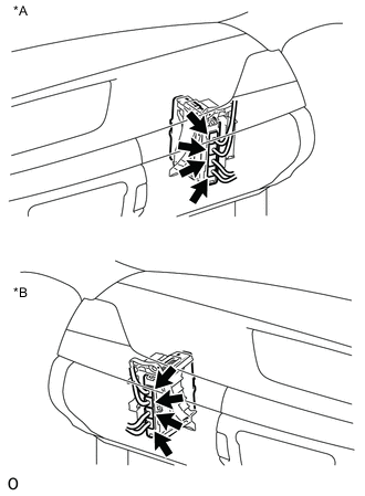
Text in Illustration *A for LHD *B for RHD Check the connector connections and contact pressure of the relevant terminals for the power management control ECU connectors Click here.
OK The connectors are connected securely and there are no contact pressure problems.
NG
CONNECT SECURELY
OK
-
-
CHECK CONNECTOR CONNECTION CONDITION (FLOOR WIRE CONNECTOR CONNECTION CONDITION)
-
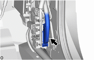
Check the connector connections and contact pressure of the relevant terminals for the floor wire connector Click here.
OK The connectors are connected securely and there are no contact pressure problems.
NG
CONNECT SECURELY
OK
-
-
CHECK CONNECTOR CONNECTION CONDITION (NO. 2 HYBRID BATTERY PACK WIRE CONNECTOR)
CAUTION:
Be sure to wear insulated gloves.
-
Check that the service plug grip is not installed.
Note
After removing the service plug grip, do not turn the power switch on (READY), unless instructed by the repair manual because this may cause a malfunction.
-
Remove the front luggage compartment trim cover Click here.
-
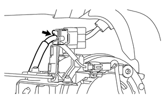
Check the connector connections and contact pressure of the relevant terminals for the No. 2 hybrid battery pack wire connector Click here.
OK The connector is connected securely and there are no contact pressure problems. -
Install the front luggage compartment trim cover.
NG
CONNECT SECURELY
OK
-
-
CHECK CONNECTOR CONNECTION CONDITION (HYBRID BATTERY JUNCTION BLOCK ASSEMBLY)
CAUTION:
Be sure to wear insulated gloves.
-
Check that the service plug grip is not installed.
Note
After removing the service plug grip, do not turn the power switch on (READY), unless instructed by the repair manual because this may cause a malfunction.
-
Remove the upper hybrid battery cover sub-assembly Click here.
-
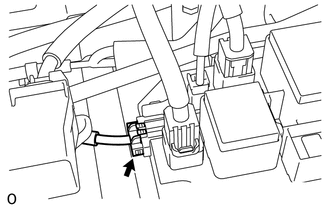
Check the connector connections and contact pressure of the relevant terminals for the hybrid battery junction block assembly connector Click here.
OK The connectors are connected securely and there are no contact pressure problems. -
Install the upper hybrid battery cover sub-assembly.
NG
CONNECT SECURELY
OK
-
-
CHECK HARNESS AND CONNECTOR (NO. 2 HYBRID BATTERY PACK WIRE CONNECTOR - POWER MANAGEMENT CONTROL ECU)
CAUTION:
Be sure to wear insulated gloves.
-
Check that the service plug grip is not installed.
Note
After removing the service plug grip, do not turn the power switch on (READY), unless instructed by the repair manual because this may cause a malfunction.
-
Remove the front luggage compartment trim cover Click here.
-
Disconnect the mT1 No. 2 hybrid battery pack wire connector.
-
Disconnect the N91 power management control ECU connector.
-
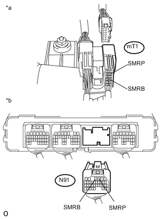
Text in Illustration *a Rear view of wire harness connector
(to No. 2 Hybrid Battery Pack Wire Connector)
*b Rear view of wire harness connector
(to Power Management Control ECU)
Measure the resistance according to the value(s) in the table below.
Standard Resistance Tester Connection Switch Condition Specified Condition mT1-4 (SMRB) - N91-4 (SMRB) Power switch off Below 1 Ω mT1-2 (SMRP) - N91-3 (SMRP) Power switch off Below 1 Ω -
Reconnect the N91 power management control ECU connector.
-
Reconnect the mT1 No. 2 hybrid battery pack wire connector.
-
Install the front luggage compartment trim cover.
NG
REPAIR OR REPLACE HARNESS OR CONNECTOR
OK
-
-
CHECK HARNESS AND CONNECTOR (NO. 2 HYBRID BATTERY PACK WIRE CONNECTOR - HYBRID BATTERY JUNCTION BLOCK ASSEMBLY)
CAUTION:
Be sure to wear insulated gloves.
-
Check that the service plug grip is not installed.
Note
After removing the service plug grip, do not turn the power switch on (READY), unless instructed by the repair manual because this may cause a malfunction.
-
Remove the front luggage compartment trim cover Click here.
-
Disconnect the mT1 No. 2 hybrid battery pack wire connector.
-
Remove the upper hybrid battery cover sub-assembly Click here.
-
Disconnect the m3 hybrid battery junction block assembly connector.
-
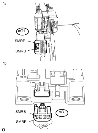
Text in Illustration *a Rear view of wire harness connector
(to No. 2 Hybrid Battery Pack Wire Connector)
*b Rear view of wire harness connector
(to Hybrid Battery Junction Block Assembly)
Measure the resistance according to the value(s) in the table below.
Standard Resistance Tester Connection Switch Condition Specified Condition mT1-4 (SMRB) - m3-4 (SMRB) Power switch off Below 1 Ω mT1-2 (SMRP) - m3-3 (SMRP) Power switch off Below 1 Ω -
Reconnect the m3 hybrid battery junction block assembly connector.
-
Install the upper hybrid battery cover sub-assembly.
-
Reconnect the mT1 No. 2 hybrid battery pack wire connector.
-
Install the front luggage compartment trim cover.
NG
REPAIR OR REPLACE HARNESS OR CONNECTOR
OK
-
-
INSPECT HV BATTERY JUNCTION BLOCK ASSEMBLY (SMRB)
CAUTION:
Be sure to wear insulated gloves.
-
Check that the service plug grip is not installed.
Note
After removing the service plug grip, do not turn the power switch on (READY), unless instructed by the repair manual because this may cause a malfunction.
-
Remove the hybrid battery junction block assembly Click here.
-
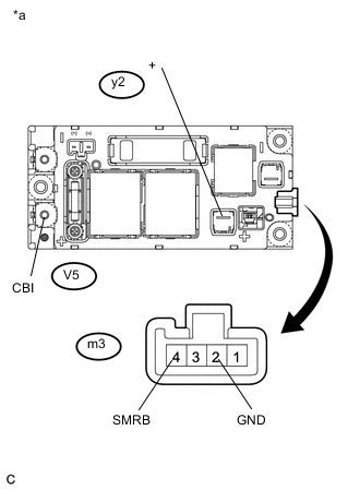
Text in Illustration *a Component without harness connected
(Hybrid Battery Junction Block Assembly)
Measure the resistance according to the value(s) in the table below.
Standard Resistance Tester Connection Condition Specified Condition V5-1 (CBI) - y2-1 (+) Auxiliary battery voltage is applied between terminals m3-4 (SMRB) and m3-2 (GND) Below 1 Ω -
Measure the resistance according to the value(s) in the table below.
Standard Resistance Tester Connection Condition Specified Condition m3-4 (SMRB) - m3-2 (GND) -40 to 80°C (-40 to 176°F) 20.6 to 40.8 Ω -
Install the hybrid battery junction block assembly
NG
REPLACE HV BATTERY JUNCTION BLOCK ASSEMBLY Click here
OK
-
-
INSPECT HV BATTERY JUNCTION BLOCK ASSEMBLY (SMRP)
CAUTION:
Be sure to wear insulated gloves.
-
Check that the service plug grip is not installed.
Note
After removing the service plug grip, do not turn the power switch on (READY), unless instructed by the repair manual because this may cause a malfunction.
-
Remove the hybrid battery junction block assembly Click here.
-
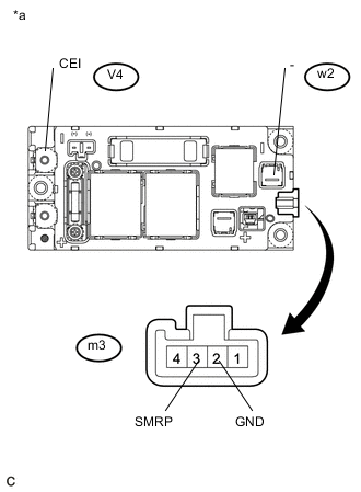
Text in Illustration *a Component without harness connected
(Hybrid Battery Junction Block Assembly)
Measure the resistance according to the value(s) in the table below.
Standard Resistance Tester Connection Condition Specified Condition V4-1 (CEI) - w2-1 (-) Auxiliary battery voltage is applied between terminals m3-3 (SMRP) and m3-2 (GND) 28.5 to 31.5 Ω -
Measure the resistance according to the value(s) in the table below.
Standard Resistance Tester Connection Condition Specified Condition m3-3 (SMRP) - m3-2 (GND) -40 to 80°C (-40 to 176°F) 140 to 290 Ω -
Install the hybrid battery junction block assembly.
NG
REPLACE HV BATTERY JUNCTION BLOCK ASSEMBLY Click here
OK
-
-
CHECK INVERTER WITH CONVERTER ASSEMBLY (NO. 4 FLOOR WIRE CONNECTOR CONNECTION CONDITION)
CAUTION:
Be sure to wear insulated gloves.
-
Check that the service plug grip is not installed.
Note
After removing the service plug grip, do not turn the power switch on (READY), unless instructed by the repair manual because this may cause a malfunction.
-
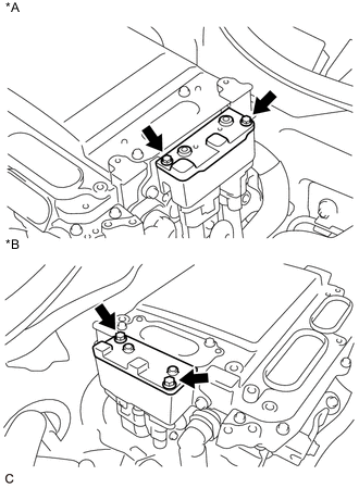
Text in Illustration *A for LHD *B for RHD Remove the connector cover assembly from the inverter with converter assembly.
-
Text in Illustration *A for LHD *B for RHD Check the connector connection condition between the No. 4 floor wire and the inverter with converter assembly.
Specified Condition 8.0 N*m (82 kgf*cm, 71 in.*lbf) -
Disconnect the connector of the No. 4 floor wire from the inverter with converter assembly.
-
Check for arc marks on the terminals of the No. 4 floor wire.
Result Result Proceed to The terminals are connected securely and there are no contact problems. There are no arc marks. A The terminals are not connected securely and there is a contact problem. There are arc marks. B The terminals are not connected securely and there is a contact problem. There are no arc marks. C The terminals are connected securely and there are no contact problems. There are arc marks. B -
Reconnect the No. 4 floor wire to the inverter with converter assembly.
-
Install the connector cover assembly to the inverter with converter assembly.
B
REPLACE MALFUNCTIONING PARTS
C
CONNECT SECURELY
A
-
-
CHECK HV BATTERY JUNCTION BLOCK ASSEMBLY (NO. 4 FLOOR WIRE CONNECTION CONDITION)
CAUTION:
Be sure to wear insulated gloves.
-
Check that the service plug grip is not installed.
Note
After removing the service plug grip, do not turn the power switch on (READY), unless instructed by the repair manual because this may cause a malfunction.
-
Remove the No. 4 hybrid vehicle battery shield sub-assembly Click here.
-
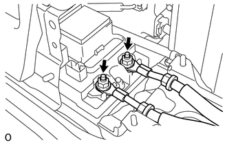
Check that the nuts for the No. 4 floor wire are tightened to the specified torque, the No. 4 floor wire is connected securely, and there are no contact problems.
Specified Condition 9.0 N*m (92 kgf*cm, 80 in.*lbf) -
Check for arc marks on the terminals of the No. 4 floor wire.
Result Result Proceed to The terminals are connected securely and there are no contact problems. There are no arc marks. A The terminals are not connected securely and there is a contact problem. There are arc marks. B The terminals are not connected securely and there is a contact problem. There are no arc marks. C The terminals are connected securely and there are no contact problems. There are arc marks. B -
Install the No. 4 hybrid vehicle battery shield sub-assembly.
B
REPLACE MALFUNCTIONING PARTS
C
CONNECT SECURELY
A
-
-
CHECK NO. 4 FLOOR WIRE (INVERTER WITH CONVERTER ASSEMBLY - HYBRID BATTERY JUNCTION BLOCK ASSEMBLY)
CAUTION:
Be sure to wear insulated gloves.
-
Check that the service plug grip is not installed.
Note
After removing the service plug grip, do not turn the power switch on (READY), unless instructed by the repair manual because this may cause a malfunction.
-
Remove the No. 4 hybrid vehicle battery shield sub-assembly Click here.
-
Remove the No. 4 floor wire from the hybrid battery junction block assembly.
-
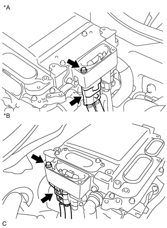
Text in Illustration *A for LHD *B for RHD Remove the connector cover assembly from the inverter with converter assembly.
-
Text in Illustration *A for LHD *B for RHD Disconnect the connector of the No. 4 floor wire from the inverter with converter assembly.
-
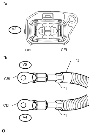
Text in Illustration *1 Shield Ground *2 Red Mark *a No. 4 Floor Wire
(Inverter with Converter Assembly Side)
*b No. 4 Floor Wire
(Hybrid Battery Junction Block Assembly Side)
Measure the resistance according to the value(s) in the table below.
Standard Resistance Tester Connection Switch Condition Specified Condition V2-1 (CBI) - V5-1 (CBI) Power switch off Below 1 Ω V2-2 (CEI) - V4-1 (CEI) Power switch off Below 1 Ω -
Reconnect the No. 4 floor wire to the inverter with converter assembly.
-
Reconnect the No. 4 floor wire to the hybrid battery junction block assembly.
-
Install the connector cover assembly.
-
Install the No. 4 hybrid vehicle battery shield sub-assembly.
NG
REPLACE NO. 4 FLOOR WIRE Click here
OK
-
-
CHECK HV BATTERY JUNCTION BLOCK ASSEMBLY (HV BATTERY HIGH VOLTAGE TERMINAL CONNECTION CONDITION)
CAUTION:
Be sure to wear insulated gloves.
-
Check that the service plug grip is not installed.
Note
After removing the service plug grip, do not turn the power switch on (READY), unless instructed by the repair manual because this may cause a malfunction.
-
Remove the upper hybrid battery cover sub-assembly Click here.
-
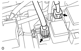
Check the connector connection condition between the 2 HV battery high voltage connectors and the hybrid battery junction block assembly.
-
Disconnect the 2 HV battery high voltage connectors from the hybrid battery junction block assembly.
-
Check for arc marks on the terminals of the HV battery high voltage terminals.
Result Result Specified Condition The terminals are connected securely and there are no contact problems. There are no arc marks. A The terminals are not connected securely and there is a contact problem. There are arc marks. B The terminals are not connected securely and there is a contact problem. There are no arc marks. C The terminals are connected securely and there are no contact problems. There are arc marks. B -
Reconnect the 2 HV battery high voltage connectors.
-
Install the upper hybrid battery cover sub-assembly.
B
REPLACE MALFUNCTIONING PARTS
C
CONNECT SECURELY
A
-
-
CHECK HV BATTERY
CAUTION:
Be sure to wear insulated gloves.
-
Check that the service plug grip is not installed.
Note
After removing the service plug grip, do not turn the power switch on (READY), unless instructed by the repair manual because this may cause a malfunction.
-
Remove the upper hybrid battery cover sub-assembly Click here.
-
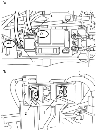
Text in Illustration *a Component with harness connected
(Hybrid Battery Junction Block Assembly)
*b Service Plug Grip Disconnected (Service Plug Grip Connecting Terminals) Measure the voltage according to the value(s) in the table below.
Standard Voltage Tester Connection Switch Condition Specified Condition y2-1 (+) - Service plug terminal 2 Power switch off 102 V or higher w2-1 (-) - Service plug terminal 1 Power switch off 90 V or higher CAUTION:
Do not allow the probes of the electrical tester to contact each other during this inspection.
-
Install the upper hybrid battery cover sub-assembly.
NG
REPLACE HV BATTERY Click here
OK
-
-
CHECK FOR INTERMITTENT PROBLEMS
-
Check for intermittent problems Click here.
Result Result Proceed to P3004-131 is not output. A P3004-131 is output again. B Tech Tips
-
Since 2 trip detection logic is used, the DTC detection condition must be met twice.
-
If DTC P3004-131 is output again after performing the inspection, replace the inverter with converter assembly. If DTC P3004-131 is not output again, replace the hybrid battery junction block assembly.
-
A
REPLACE HV BATTERY JUNCTION BLOCK ASSEMBLY Click here
B
REPLACE INVERTER WITH CONVERTER ASSEMBLY Click here
-