HYBRID CONTROL SYSTEM, Diagnostic DTC:P0A93-346
| DTC Code | DTC Name |
|---|---|
| P0A93-346 | Inverter Cooling System Performance |
DESCRIPTION
The inverter converts the high-voltage direct current of the HV battery into alternating current for generator (MG1) and motor (MG2). The inverter generates heat during the conversion process. Therefore, the inverter is cooled by a special cooling system consisting of the inverter water pump with motor assembly, the cooling fan, and a radiator. This cooling system is independent of the engine cooling system. The power management control ECU monitors the inverter water pump with motor assembly, cooling fan and cooling system, and detects malfunctions.
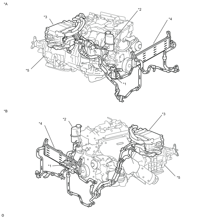
| *A | for LHD | *B | for RHD |
| *1 | Inverter Water Pump with Motor Assembly | *2 | Inverter Reserve Tank Assembly |
| *3 | Inverter with Converter Assembly | *4 | Radiator Assembly (HV) |
| *5 | Hybrid Vehicle Transmission Assembly | - | - |
| DTC No. | DTC Detection Condition | Trouble Area |
|---|---|---|
| P0A93-346 | Inverter coolant temperature increases as well as the temperature of any inverter with converter assembly related parts increases. (1 trip detection logic) |
|
| DTC No. | Data List |
|---|---|
| P0A93-346 |
|
CAUTION / NOTICE / HINT
CAUTION:
-
Before inspecting the high-voltage system or disconnecting the low voltage connector of the inverter with converter assembly, take safety precautions such as wearing insulated gloves and removing the service plug grip to prevent electrical shocks. After removing the service plug grip, put it in your pocket to prevent other technicians from accidentally reconnecting it while you are working on the high-voltage system.
-
After removing the service plug grip, wait for at least 10 minutes before touching any of the high-voltage connectors or terminals. After waiting for 10 minutes, check the voltage at the terminals in the inspection point in the inverter with converter assembly. The voltage should be 0 V before beginning work Click here.
Tech Tips
Waiting for at least 10 minutes is required to discharge the high-voltage capacitor inside the inverter with converter assembly.
Note
-
After turning the power switch off, waiting time may be required before disconnecting the cable from the negative (-) auxiliary battery terminal. Therefore, make sure to read the disconnecting the cable from the negative (-) auxiliary battery terminal notices before proceeding with work Click here.
-
If DTC P0A78-284, 286, P0A7A-322, 324, P0A94-553 or 557 is output, replace the inverter with converter assembly after this inspection.
Tech Tips
After the repair, clear the DTCs and perform the following procedure to check that DTCs are not output.
-
Perform a road test according to the freeze frame data "Vehicle Spd" for approximately 15 minutes.
During the road test, check Data List items "Inverter Coolant Water Temperature", "Inverter Temp-(MG2)", "Inverter Temp- (MG1)", "DC/DC Cnv Temp (Upper)" and " DC/DC Cnv Temp (Lower)" to prevent the relevant parts from overheating.
PROCEDURE
-
CHECK VEHICLE CONDITION
-
Make sure that the front side of the radiator grille is not blocked with anything.
-
Ask the customer if the front side of the radiator grille was blocked with anything.
Result Result Proceed to Not blocked. A Is/was blocked. B Tech Tips
If the radiator grille is blocked, the inverter coolant temperature will increase and this DTC may be stored.
B 
IF EQUIPPED, EXPLAIN TO CUSTOMER THAT OPTIONAL COMPONENTS WILL BE REMOVED
A 
-
-
CHECK DTC OUTPUT (HYBRID CONTROL)
-
Connect the GTS to the DLC3.
-
Turn the power switch on (IG).
-
Enter the following menus: Powertrain / Hybrid Control / Trouble Codes.
-
Check for DTCs.
Result Result Proceed to P0A93-346 only is output, or DTCs except the ones in the table below are also output. A Any of the following DTCs are also output. B Relevant DTC P0A02-719 Motor Electronics Coolant Temperature Sensor Circuit Low P0A03-720 Motor Electronics Coolant Temperature Sensor Circuit High P0C73-776 Motor Electronics Coolant Pump "A" Control Performance P314A-828 Inverter Coolant Pump Speed Signal Tech Tips
P0A93-346 may be stored due to a malfunction which also causes DTCs in the preceding table to be stored. In this case, first troubleshoot the output DTCs in the preceding table. Then, perform a test to attempt to reproduce the problems, and check that no DTCs are output.
-
Turn the power switch off.
B
GO TO DTC CHART (HYBRID CONTROL SYSTEM) Click here
A
-
-
CHECK CONNECTOR CONNECTION CONDITION (INVERTER WITH CONVERTER ASSEMBLY CONNECTOR)
CAUTION:
Be sure to wear insulated gloves.
-
Check that the service plug grip is not installed.
Note
After removing the service plug grip, do not turn the power switch on (READY), unless instructed by the repair manual because this may cause a malfunction.
-
Check connection condition of the low voltage connector of the inverter with converter assembly and the contact pressure of each terminal. Check the terminals for deformation, and check the connector for water ingress and foreign matter Click here.
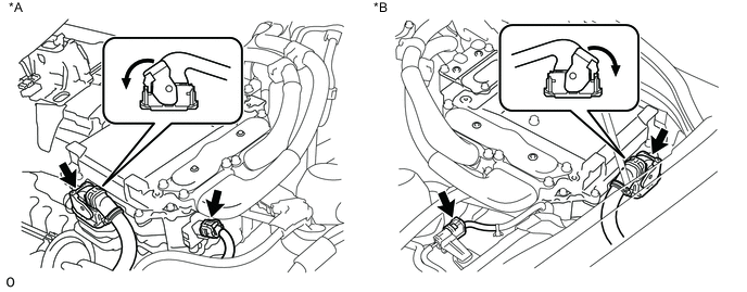
Text in Illustration *A for LHD *B for RHD Note
Before disconnecting the connector, confirm that it is properly connected by checking that the locking claws are engaged and that the connector does not pull out.
OK - The connector is connected securely. - The terminals are not deformed and are connected securely. - No water or foreign matter in the connector. Result Result Proceed to OK A NG (The connector is not connected securely.) B NG (The terminals are not making secure contact or are deformed, or water or foreign matter exists in the connector.) C Tech Tips
When connecting the connector, insert it with the locking lever in the raised position. Rotate the lever downward and make sure that the connector is pulled into its socket. When the locking lever is in its fully closed position, a click will be heard as its locking claws engage. After the click is heard, pull up on the connector to confirm that it is properly connected.
B
CONNECT SECURELY
C
REPAIR OR REPLACE HARNESS OR CONNECTOR
A
-
-
CHECK QUANTITY OF HV COOLANT
-
Check the HV coolant level in the inverter reserve tank.
-
Check for HV coolant leaks.
Result Result Proceed to No leaks are found and coolant level in the inverter reserve tank assembly is above the low line. A No leaks are found and coolant level in the inverter reserve tank assembly is below the low line. B HV coolant leaks are evident. C Note
The inverter water pump with motor assembly has a protection function that activates when there is an HV coolant leak. Therefore, it is not necessary to replace the inverter water pump with motor assembly unless the cause of the HV coolant leak is the inverter water pump with motor assembly.
Tech Tips
After repairing the HV coolant leaks and adding coolant, perform the "(Inverter) " Active Test (HV Active Test item) and the "Control the Electric Cooling Fan" Active Test (Engine Active Test item) and make sure that there are no malfunctions.
B
ADD HV COOLANT
C
INSPECT FOR HV COOLANT LEAK AND ADD HV COOLANT
A
-
-
CHECK COOLANT HOSE
-
Check that the cooling system hoses are not kinked or clogged.
NG
REPAIR OR REPLACE COOLANT HOSE
OK
-
-
PERFORM ACTIVE TEST USING GTS (CONTROL THE ELECTRIC COOLING FAN)
-
Connect the GTS to the DLC3.
-
Turn the power switch on (IG).
-
Enter the following menus: Powertrain / Engine and ECT / Active Test / Control the Electric Cooling Fan.
-
Perform the "Control the Electric Cooling Fan" Active Test.
OK The cooling fan rotates. -
Turn the power switch off.
NG
CHECK COOLING FAN SYSTEM Click here
OK
-
-
PERFORM ACTIVE TEST USING GTS (ACTIVATE THE (INVERTER) WATER PUMP)
Note
Be sure to perform the inspection with the auxiliary battery voltage at 11 V or more.
Tech Tips
When the auxiliary battery voltage is low, the inverter water pump with motor assembly may not operate.
-
Connect the GTS to the DLC3.
-
Turn the power switch on (IG).
-
Enter the following menus: Powertrain / Hybrid Control / Active Test / Activate the (Inverter) Water Pump.
-
Select Inverter W/P Revolution in the Data List.
-
While performing the "Activate the (Inverter) Water Pump" Active Test, check Inverter W/P Revolution in the Data List.
Result Tester Display Switch Condition Specified Condition Inverter W/P Revolution Power switch on (IG) 2375 to 5750 rpm Tech Tips
-
Perform the Active Test with the inverter coolant temperature between -15 and 65°C (5 to 149°F).
-
When the inverter water pump with motor assembly is not operating, the Data List item "Inverter W/P Revolution" displays a value lower than 625 rpm.
-
-
Turn the power switch off.
NG 
CHECK CONNECTOR CONNECTION CONDITION (POWER MANAGEMENT CONTROL ECU CONNECTOR) Click here
OK
-
-
READ VALUE USING GTS (DATA LIST)
-
Turn the power switch off and leave the vehicle for at least 1 hour.
-
Connect the GTS to the DLC3.
-
Turn the power switch on (IG).
-
Enter the following menus: Powertrain / Hybrid Control / Data List / Inverter Coolant Water Temperature, Inverter Temp (MG2), Cnv Tmp (Upper), Cnv Temp (Lower), Inverter Temp (MG1).
-
Read the Data List.
Result Result Proceed to Other than below. A "Inverter Coolant Water Temperature" value is higher than the displayed temperature of any other Data List item by 20°C (68°F) or more. B Tech Tips
The lower limit temperature that can be displayed for "Inverter Temp- (MG1)", "Inverter Temp- (MG2)", "Cnv Tmp (Upper)" and "Cnv Temp (Lower)" is 15°C (59°F). The lower limit temperature for "Inverter Coolant Water Temperature" is -40°C (-40°F). The "Inverter Coolant Water Temperature" value displayed on the GTS may be lower than the others, but this is not a malfunction.
-
Turn the power switch off.
B
REPLACE INVERTER WITH CONVERTER ASSEMBLY Click here
A
-
-
REPLACE HV COOLANT
-
Replace the HV coolant with coolant having an appropriate concentration (appropriate freeze point) for the vehicle usage conditions Click here.
NEXT
COMPLETED
-
-
CHECK CONNECTOR CONNECTION CONDITION (POWER MANAGEMENT CONTROL ECU CONNECTOR)
-
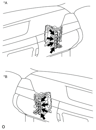
Text in Illustration *A for LHD *B for RHD Check the connector connections and contact pressure of the relevant terminals for the power management control ECU connectors Click here.
OK The connectors are connected securely and there are no contact pressure problems.
NG
CONNECT SECURELY
OK
-
-
CHECK CONNECTOR CONNECTION CONDITION (INVERTER WATER PUMP WITH MOTOR ASSEMBLY CONNECTOR)
-
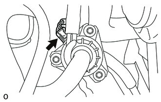
Check the connector connections and contact pressure of the relevant terminals for the inverter water pump with motor assembly connector Click here.
OK The connectors are connected securely and there are no contact pressure problems.
NG
CONNECT SECURELY
OK
-
-
CHECK HARNESS AND CONNECTOR (POWER MANAGEMENT CONTROL ECU - INVERTER WATER PUMP WITH MOTOR ASSEMBLY)
-
Disconnect the A35 power management control ECU connector.
-
Disconnect the A26 inverter water pump with motor assembly connector.
-
Measure the resistance according to the value(s) in the table below.
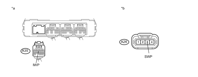
Text in Illustration *a Rear view of wire harness connector
(to Power Management Control ECU)
*b Front view of wire harness connector
(to Inverter Water Pump with Motor Assembly)
Standard Resistance (Check for Open) Tester Connection Switch Condition Specified Condition A35-13 (IWP) - A26-3 (SWP) Power switch off Below 1 Ω Standard Resistance (Check for Short) Tester Connection Switch Condition Specified Condition A35-13 (IWP) or A26-3 (SWP) - Body ground and other terminals Power switch off 10 kΩ or higher -
Reconnect the A26 inverter water pump with motor assembly connector.
-
Reconnect the A35 power management control ECU connector.
NG
REPAIR OR REPLACE HARNESS OR CONNECTOR
OK
-
-
READ VALUE USING GTS (INVERTER W/P REVOLUTION)
Note
Be sure to perform the inspection with the auxiliary battery voltage at 11 V or more.
Tech Tips
When the auxiliary battery voltage is low, the inverter water pump with motor assembly may not operate.
-
Connect the GTS to the DLC3.
-
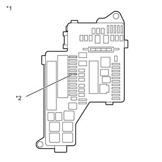
Text in Illustration *1 No. 1 Engine Room Relay Block and Junction Block Assembly *2 INV W/P Fuse Remove the INV W/P fuse from the No. 1 engine room relay block and junction block assembly.
-
Turn the power switch on (IG).
-
Enter the following menus: Powertrain / Hybrid Control / Data List / Inverter W/P Revolution.
-
Read the Data List.
Result Tester Display Switch Condition Specified Condition Inverter W/P Revolution Power switch on (IG) 125 rpm or less -
Turn the power switch off.
-
Install the INV W/P fuse.
NG
REPLACE POWER MANAGEMENT CONTROL ECU Click here
OK
-
-
CHECK HARNESS AND CONNECTOR (POWER MANAGEMENT CONTROL ECU - INVERTER WATER PUMP WITH MOTOR ASSEMBLY)
-
Disconnect the A35 power management control ECU connector.
-
Turn the power switch on (IG).
-
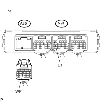
Text in Illustration *a Rear view of wire harness connector
(to Power Management Control ECU)
Measure the voltage according to the value(s) in the table below.
Standard Voltage Tester Display Switch Condition Specified Condition A35-13 (IWP) - N91-6 (E1) Power switch on (IG) 11 to 14 V Note
Turning the power switch on (IG) with the power management control ECU connector disconnected causes other DTCs to be stored. Clear the DTCs after performing this inspection.
-
Turn the power switch off.
-
Reconnect the A35 power management control ECU connector.
NG
REPLACE INVERTER WATER PUMP WITH MOTOR ASSEMBLY Click here
OK
-
-
CHECK POWER MANAGEMENT CONTROL ECU (CHECK WAVEFORM)
-
Connect an oscilloscope between the power management control ECU terminals specified in the table below.
-
Turn the power switch on (IG).
-
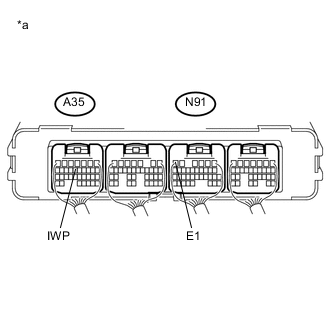
Text in Illustration *a Component with harness connected
(Power Management Control ECU)
While turning the power switch on (IG), check the waveform between the power management control ECU terminals.
Item Condition Terminal A35-13 (IWP) - N91-6 (E1) Equipment Setting 5 V/DIV., 50 ms./DIV. Condition Power switch on (IG) OK Waveform duty ratio is between 3% and 9%. -
Turn the power switch off.
OK
REPLACE INVERTER WATER PUMP WITH MOTOR ASSEMBLY Click here
NG
REPLACE POWER MANAGEMENT CONTROL ECU Click here
-