SFI SYSTEM, Diagnostic DTC:P011B
| DTC Code | DTC Name |
|---|---|
| P011B | Engine Coolant Temperature / Intake Air Temperature Correlation |
DESCRIPTION
The engine has 2 temperature sensors, an engine coolant temperature sensor and an intake air temperature sensor, to detect the temperature while the engine is operating. A thermistor, whose resistance value varies according to the temperature, is built into each sensor. When the temperature is low, the resistance of the thermistor increases. When the temperature is high, the resistance drops. These variations in resistance are transmitted to the ECM as voltage changes. Based on these temperature signals output from the sensors, the ECM determines the fuel injection duration and the ignition during to control the engine.
| DTC No. | DTC Detection Condition | Trouble Area |
|---|---|---|
| P011B |
|
|
Tech Tips
-
Waiting is required to prevent the temperature of the engine from affecting the readings. If the engine has been operated recently, it will not be possible to accurately compare the readings.
-
For diagnosis, in order to duplicate the detection conditions of the DTC, it is necessary to park the vehicle for 7 hours. Parking the vehicle for 7 hours ensures that the actual temperature of the engine coolant temperature and intake air temperature are very similar. When the vehicle has been parked for less than 7 hours, differences in the readings may exist. This does not necessarily indicate a fault.
MONITOR DESCRIPTION
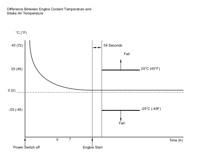
The ECM monitors the difference between the engine coolant temperature and the intake air temperature when the engine is started cold to detect the engine temperature conditions accurately. The monitor runs when the engine started cold after 7 hours or more has elapsed since the engine was stopped (power switch turned off) on the previous trip. If the difference between the engine coolant temperature and the intake air temperature on a cold start exceeds 25°C (45°F), the ECM interprets this as a malfunction in the engine coolant temperature sensor circuit and intake air temperature sensor circuit, and sets the DTC.
MONITOR STRATEGY
| Frequency of Operation | Once per driving cycle |
CONFIRMATION DRIVING PATTERN
-
Connect the GTS to the DLC3.
-
Turn the power switch on (IG) and turn the GTS on.
-
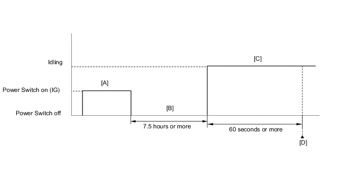
Clear the DTCs (even if no DTCs are stored, perform the clear DTC procedure) Click here [A].
-
Turn the power switch off and wait for at least 30 seconds.
-
With the engine stopped, leave the vehicle as is for 7.5 hours or more [B].
-
Turn the power switch on (IG) and turn the GTS on.
-
Put the engine in inspection mode (maintenance mode) Click here.
-
Start the engine and wait 60 seconds or more [C].
-
Enter the following menus: Powertrain / Engine and ECT / Trouble Codes [D].
-
Read the pending DTC.
Tech Tips
-
If a pending DTC is output, the system is malfunctioning.
-
If a pending DTC is not output, perform the following procedure.
-
-
Enter the following menus: Powertrain / Engine and ECT / Utility / All Readiness.
-
Input the DTC: P011B.
-
Check the DTC judgment result.
GTS Display Description NORMAL
-
DTC judgment completed
-
System normal
ABNORMAL
-
DTC judgment completed
-
System abnormal
INCOMPLETE
-
DTC judgment not completed
-
Perform driving pattern after confirming DTC enabling conditions
N/A
-
Unable to perform DTC judgment
-
Number of DTCs which do not fulfill DTC preconditions has reached ECU memory limit
Tech Tips
-
If the judgment result shows ABNORMAL, the system has a malfunction.
-
If the judgment result shows NORMAL, the system is normal.
-
If the judgment result shows INCOMPLETE or N/A, perform steps [A] through [C] again.
-
CAUTION / NOTICE / HINT
Tech Tips
Read freeze frame data using the GTS. The ECM records vehicle and driving condition information as freeze frame data the moment a DTC is stored. When troubleshooting, freeze frame data can help determine if the vehicle was moving or stationary, if the engine was warmed up or not, if the air fuel ratio was lean or rich, and other data from the time the malfunction occurred.
PROCEDURE
-
CHECK ANY OTHER DTCS OUTPUT (IN ADDITION TO DTC P011B)
-
Connect the GTS to the DLC3.
-
Turn the power switch on (IG).
-
Turn the GTS on.
-
Enter the following menus: Powertrain / Engine and ECT / Trouble Codes.
-
Read the DTCs.
Result Result Proceed to DTC P011B is output A DTC P011B and other DTCs are output B Tech Tips
If any DTCs other than P011B are output, troubleshoot those DTCs first.
B 
GO TO DTC CHART Click here
A 
-
-
READ VALUE USING GTS (INTAKE AIR)
-
Leave the vehicle for 7 hours or more.
Tech Tips
It is necessary to leave the vehicle for 7 hours or more to allow conditions similar to the DTC detection conditions.
-
Connect the GTS to the DLC3.
-
Turn the power switch on (IG).
-
Turn the GTS on.
-
Enter the following menus: Powertrain / Engine and ECT / Data List / Intake Air.
-
Read the value displayed on the GTS.
OK Difference between the intake air temperature and the actual outside air temperature is within 10°C (18°F). Tech Tips
-
Intake air temperature readings on the vehicle outside temperature gauge (if equipped) are not suitable for comparing to the intake air temperature reading. The outside temperature gauge has a significant delay built in to prevent temperature swings from being displayed on its display. Use an accurate thermometer to determine the outside air temperature.
-
Perform "Inspection After Repair" after replacing the mass air flow meter Click here.
-
NG
REPLACE MASS AIR FLOW METER Click here
OK
-
-
READ VALUE USING GTS (COOLANT TEMP)
-
Connect the GTS to the DLC3.
-
Turn the power switch on (IG).
-
Turn the GTS on.
-
Enter the following menus: Powertrain / Engine and ECT / Data List / Coolant Temp.
-
Read the value displayed on the GTS.
OK Difference between the coolant temperature and the actual outside air temperature is within 10°C (18°F). Tech Tips
-
If the result is not as specified, check if there are heat sources such as a block heater in the engine compartment.
-
Perform "Inspection After Repair" after replacing the engine coolant temperature sensor Click here.
-
OK
REPLACE ECM Click here
NG
REPLACE ENGINE COOLANT TEMPERATURE SENSOR Click here
-