SFI SYSTEM, Diagnostic DTC:P0087
| DTC Code | DTC Name |
|---|---|
| P0087 | Fuel Rail / System Pressure - Too Low |
DESCRIPTION
The high-pressure fuel system consists of the spill control valve, pump plunger, check valve, relief valve and fuel pressure sensor. The spill control valve opens and closes the low-pressure fuel line (from the fuel tank), the pump plunger (operated by the camshaft) pressurizes fuel, the check valve mechanically opens and closes the high pressure fuel line (to the fuel delivery pipe), the relief valve prevents fuel pressure from becoming extremely high, and the fuel pressure sensor located on the fuel delivery pipe monitors fuel pressure.
The fuel pump for high pressure is installed to the cylinder head cover (bank 1) and is driven by the cam located at the rear end of the exhaust camshaft.
The plunger moves up and down by the camshaft rotations, and produces a vacuum to suck fuel and pressurizes the fuel. This fuel then pushes the check valve open and flows into the fuel delivery pipe. The ECM opens and closes the spill control valve to regulate the fuel pressure to the target fuel pressure of 2 to 18 MPa (20.4 to 183.5 kgf/cm2, 290 to 2609 psi). In order to obtain and maintain the target pressure, the ECM monitors the fuel pressure using the fuel pressure sensor and performs the feedback control.
If the internal fuel pressure of the fuel delivery pipe exceeds the standard pressure of 25.0 MPa (255.0 kgf/cm2, 3626 psi), the fuel relief valve installed on gateway of the fuel delivery pipe discharges the fuel pressure and then returns the fuel back to the fuel tank.
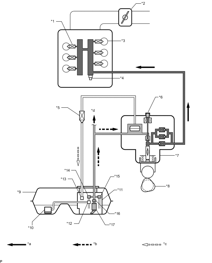
| *1 | Fuel Injector Assembly | *2 | Throttle body with motor assembly |
| *3 | Cylinder | *4 | Fuel Pressure Sensor |
| *5 | Solenoid Valve (Fuel Return Pipe Valve) | *6 | Solenoid Spill Valve |
| *7 | Fuel Pump Assembly (for High Pressure) | *8 | Camshaft |
| *9 | Fuel Tank Assembly | *10 | Fuel Tank Vent Tube Assembly - No. 2 Fuel Sender Gauge Assembly |
| *11 | Fuel Suction Tube Assembly with Pump and Gauge - Fuel Sender Gauge Assembly |
*12 | Jet Pump |
| *13 | Fuel Main Valve Assembly (Return) | *14 | Fuel Main Valve Assembly |
| *15 | Fuel Pressure Regulator Assembly | *16 | Fuel Filter |
| *17 | Fuel Pump Assembly | - | - |
| *a | High Pressure Fuel Line | *b | Low Pressure Fuel Line |
| *c | Return Fuel Line | *d | To Fuel Injector Assembly (for Port Injection) |
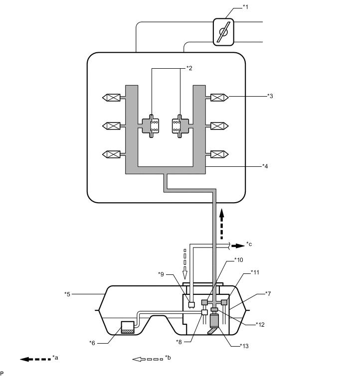
| *1 | Throttle body with motor assembly | *2 | Fuel Pressure Pulsation Damper Assembly |
| *3 | Fuel Injector Assembly | *4 | Fuel Delivery Pipe |
| *5 | Fuel Tank Assembly | *6 | Fuel Tank Vent Tube Assembly - No. 2 Fuel Sender Gauge Assembly |
| *7 | Fuel Suction Tube Assembly with Pump and Gauge - Fuel Sender Gauge Assembly |
*8 | Jet Pump |
| *9 | Fuel Main Valve Assembly | *10 | Fuel Pressure Regulator Assembly |
| *11 | Fuel Filter | *12 | Fuel Pump Assembly |
| *a | Low Pressure Fuel Line | *b | To Fuel Pump Assembly (for High Pressure) |
| DTC No. | DTC Detection Condition | Trouble Area |
|---|---|---|
| P0087 | Despite ECM commanding that the high pressure fuel pump opens the spill valve, fuel pressure decreases 5 MPa (51.0 kgf/cm2, 725 psi) while the engine is not idling, or 3 MPa (30.6 kgf/cm2, 435 psi) while the engine is idling from target fuel pressure for about 10 seconds (1 trip detection logic) |
|
MONITOR DESCRIPTION
If the fuel pressure decreases even after the ECM commands the high-pressure fuel pump to close the spill control valve, a DTC is output.
MONITOR STRATEGY
| Required sensors/Components | Fuel pressure sensor |
| Frequency of operation | Continuous |
CONFIRMATION DRIVING PATTERN
-
Connect the GTS to the DLC3.
-
Turn the power switch on (IG) and turn the GTS on.
-
Record the Freeze Frame Data.
-
Clear the DTCs (even if no DTCs are stored, perform the clear DTC procedure) Click here.
-
Turn the power switch off and wait for at least 30 seconds.
-
Turn the power switch on (IG) and turn the GTS on.
-
Based on engine speed, engine load and other freeze frame data stored in the ECM, reproduce the conditions present when the DTC was stored.
-
Enter the following menus: Powertrain / Engine and ECT / Trouble Codes.
-
Read the DTC.
Tech Tips
-
If a DTC is output, the system is malfunctioning.
-
If a DTC is not output, perform the following procedure.
-
-
Enter the following menus: Powertrain / Engine and ECT / Utility / All Readiness.
-
Input the DTC: P0087.
-
Check the DTC judgment result.
GTS Display Description NORMAL
-
DTC judgment completed
-
System normal
ABNORMAL
-
DTC judgment completed
-
System abnormal
INCOMPLETE
-
DTC judgment not completed
-
Perform driving pattern after confirming DTC enabling conditions
N/A
-
Unable to perform DTC judgment
-
Number of DTCs which do not fulfill DTC preconditions has reached ECU's memory limit
Tech Tips
-
If the judgment result shown ABNORMAL, the system has a malfunction.
-
If the judgment result shows NORMAL, the system is normal.
-
CAUTION / NOTICE / HINT
Tech Tips
Read freeze frame data using the GTS. The ECM records vehicle and driving condition information as freeze frame data the moment a DTC is stored. When troubleshooting, freeze frame data can be helpful in determining whether the vehicle was moving or stationary, whether the engine was warmed up or not, whether the air fuel ratio was lean or rich, as well as other data recorded at the time of a malfunction.
PROCEDURE
-
CHECK FUEL LEAK (HIGH PRESSURE SIDE)
-
Check around and beneath the car for fuel leaks, fumes, etc.
OK No fuel leaks present.
NG 
REPAIR OR REPLACE FUEL LEAK POINT
OK 
-
-
CHECK OTHER DTCS OUTPUT (IN ADDITION TO DTC P0087)
-
Connect the GTS to the DLC3.
-
Turn the power switch on (IG) and turn the GTS on.
-
Enter the following menus: Powertrain / Engine and ECT / Trouble Codes.
-
Read the DTCs.
Result Result Proceed to DTC P0087 is output A DTC P0087 and other DTCs are output B Tech Tips
If any DTCs other than P0087 are output, troubleshoot those DTCs first.
B
GO TO DTC CHART Click here
A
-
-
CHECK FUEL PRESSURE (LOW PRESSURE SIDE)
-
Check the fuel pressure Click here.
NG 
CHECK FUEL PUMP OPERATION Click here
OK
-
-
CHECK MISFIRE COUNT
-
Connect the GTS to the DLC3.
-
Turn the power switch on (IG) and turn the GTS on.
-
Start the engine.
-
Enter the following menus: Powertrain / Engine and ECT / Active Test / Control the Injection Way / Direct.
-
Allow the engine to idle.
-
Monitor all of the misfire count values that are displayed on the GTS: Powertrain / Engine and ECT / Data List / Misfire / Cylinder #1 Misfire count to Cylinder #6 Misfire count.
If no misfire counts occur for any of the cylinders, perform the following procedure:
-
Move the shift lever to D.
-
Monitor all of the misfire rate values that are displayed on the GTS.
Result Misfire Count Proceed to No misfire counts, or misfire counts occur randomly in all cylinders A Misfire counts occur in a particular cylinder B
-
B
REPLACE FUEL INJECTOR FOR DIRECT INJECTION Click here
A
-
-
REPLACE FUEL PUMP ASSEMBLY (FOR HIGH PRESSURE)
-
Replace the fuel pump assembly (for high pressure) Click here.
NEXT
-
-
CHECK WHETHER DTC OUTPUT RECURS
-
Connect the GTS to the DLC3.
-
Turn the power switch on (IG) and turn the GTS on.
-
Clear the DTCs.
-
Drive the vehicle in accordance with the driving pattern described in the Confirmation Driving Pattern.
-
Enter the following menus: Powertrain / Engine and ECT / Trouble Codes.
-
Read the DTCs.
Result Result Proceed to DTC P0087 is output A DTC is not output B
A
REPLACE ECM Click here
B
END
-
-
CHECK FUEL PUMP OPERATION
-
Check the fuel pump operation Click here.
OK
CHECK AND REPLACE FUEL SYSTEM (PRESSURE REGULATOR, PIPE LINE AND FILTER)
NG
REPLACE FUEL PUMP (LOW PRESSURE SIDE) Click here
-