HEADLIGHT ASSEMBLY(for Single Beam Headlight) DISASSEMBLY

CAUTION / NOTICE / HINT
Note
-
Be sure to read Precaution thoroughly before servicing.
-
Handle components indoors as much as possible to prevent foreign matter from entering and adhering to headlight assembly components.
-
Do not reuse parts which have reduced fastening ability due to thread damage.
-
Do not touch the inner surface of the lens and metallic surfaces as much as possible, or they may become dirty
-
Do not allow metallic surfaces to become dirty, as such surfaces become damaged even if they are only lightly wiped with a soft cloth.
-
When installing components, make sure that the wire harness is not pinched or pulled.
-
Do not use solvent to clean components. Only clean them with a dry cloth.
Tech Tips
-
Use the same procedure for the RH and LH sides.
-
The procedure described below is for the LH side.
PROCEDURE
-
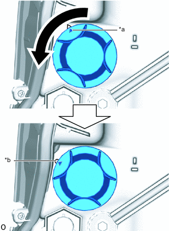
REMOVE FRONT TURN SIGNAL LIGHT BULB
-
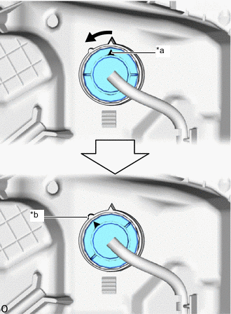
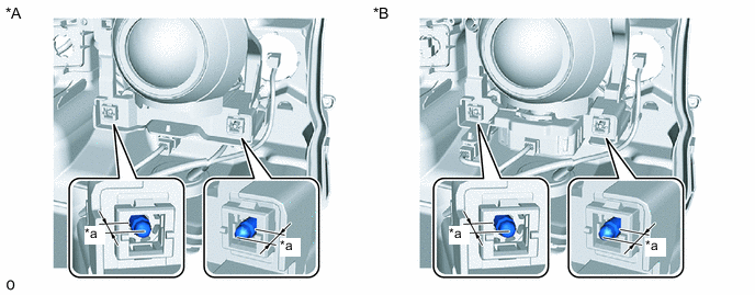
Text in Illustration *a Matchmark *b Unlock Position Mark Turn the bulb socket counterclockwise until the matchmark is aligned with the unlock position mark to disconnect the bulb socket.
-
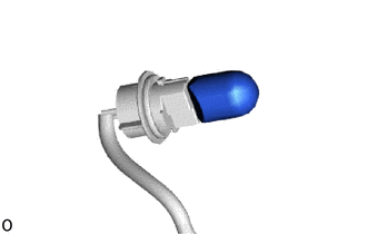
Remove the front turn signal light bulb from the bulb socket.
-
-
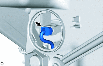
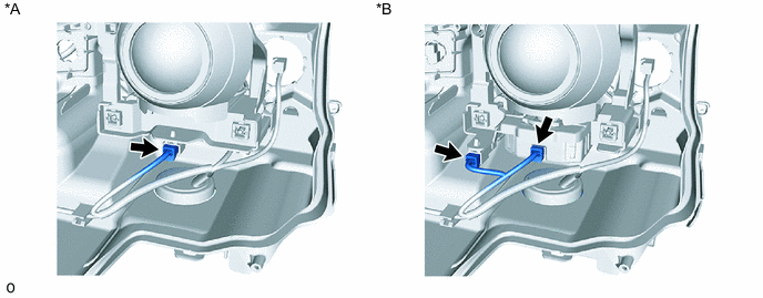
REMOVE HEADLIGHT CORD
-
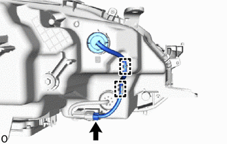
Disconnect the 2 wire harness clamps and connector to remove the headlight cord.
-
-
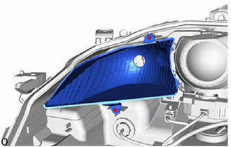
REMOVE HEADLIGHT COVER LH
-
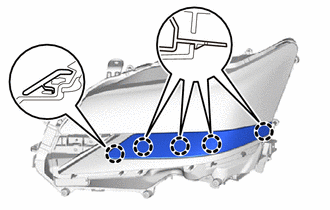
Detach the 5 claws to remove the headlight cover LH.
-
-
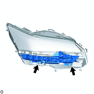
REMOVE HEADLIGHT BRACKET LH (for Outside)
-
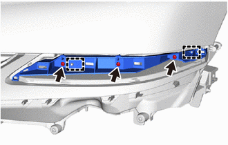
Remove the 3 screws.
-
Detach the 2 guides to remove the headlight bracket LH.
-
-
REMOVE HEADLIGHT BRACKET LH (for Inside)
-
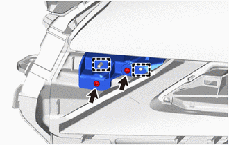
Remove the 2 screws.
-
Detach the 2 guides to remove the headlight bracket LH.
-
-
REMOVE HEADLIGHT ECU SUB-ASSEMBLY LH
-
REMOVE HEADLIGHT GASKET
-
REMOVE HEADLIGHT LENS LH
Note
-
Perform work using clean rubber gloves.
-
Do not touch the inner surface of the lens.
-
If there are fingerprints on the inner surface of the lens, lightly wiped with a soft cloth.
-
Do not use solvent to clean components. Only clean them with a dry cloth.
-
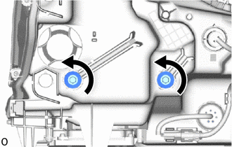
Text in Illustration *a Matchmark *b Unlock Position Mark Turn the headlight socket cover counterclockwise until the matchmark is aligned with the unlock position mark to remove the headlight socket cover.
-
Disconnect the connector.
-
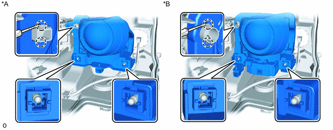
Remove the 6 screws.
-
Using a T20H "TORX" driver, remove the 3 "TORX" screws.
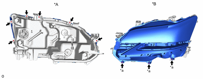
Text in Illustration *A Headlight Assembly LH Backside *B Headlight Assembly LH Surface *a "TORX Screw - - -
Using a dryer, warm the headlight lens gasket from the backside of the headlight assembly LH at the separation starting point of the headlight lens LH and headlight housing.
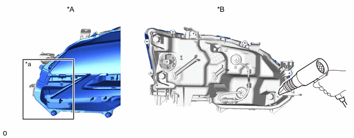
Text in Illustration *A Headlight Assembly LH Backside *B Headlight Assembly LH Surface *a Separation Starting Point - - Note
If the headlight is heated unevenly, it will deform or melt.
Tech Tips
-
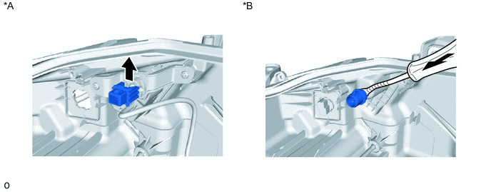
If the headlight lens LH cannot be lifted, even after heating, using a screwdriver, lift the headlight lens LH.
-
Tape the screwdriver tip before use.
-
-
Detach the 3 claws A and slightly lift the headlight lens LH.
-
Heat the headlight lens gasket starting from the backside of the headlight assembly LH and finishing at the area around claw B.
-
Detach the 2 claws B and claw C to remove the headlight lens LH.
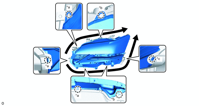
Text in Illustration *a Claw A *b Claw B *c Claw C - -
-
-
REMOVE HEADLIGHT LENS GASKET
Note
-
Perform work using clean rubber gloves.
-
Do not touch the inner surface of the lens and metallic surfaces as much as possible, or they may become dirty.
-
Do not allow metallic surfaces to become dirty, as such surfaces become damaged even if they are only lightly wiped with a soft cloth.
-
If there are fingerprints on the inner surface of the lens, lightly wiped with a soft cloth.
-
Do not use solvent to clean components. Only clean them with a dry cloth.
-
The gasket must not be reused.
-
Remove the headlight lens gasket from the headlight lens and headlight housing.
-
-
REMOVE NO. 1 HEADLIGHT CLEARANCE LED UNIT LH
Note
-
Prevention of static electricity is required during this procedure.
-
Use static electricity countermeasures SST (desktop antistatic mat set) and observe all precautions to prevent damage to the system by electrostatic discharge (ESD).
-
Perform work using clean rubber gloves.
-
Do not touch the headlight inner bezel and No. 1 headlight clearance LED unit LH with bare hands.
-
Do not allow metallic surfaces to become dirty, as such surfaces become damaged even if they are only lightly wiped with a soft cloth.
-
Do not use solvent to clean components. Only clean them with a dry cloth.
- SST
- 09890-47010 ( 09891-04010, 09891-04020, 09891-04030, 09891-04040 )
-
Disconnect the connector.
-
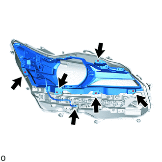
Remove the 5 screws and headlight inner bezel.
-
Remove the 2 screws and lower side of the No 1 headlight clearance LED unit LH.
-
-
REMOVE HEADLIGHT UNIT ASSEMBLY LH
Note
-
Prevention of static electricity is required during this procedure.
-
Use static electricity countermeasures SST (desktop antistatic mat set) and observe all precautions to prevent damage to the system by electrostatic discharge (ESD).
-
Perform work using clean rubber gloves.
-
Do not touch the headlight unit assembly LH with bare hands.
-
Do not allow metallic surfaces to become dirty, as such surfaces become damaged even if they are only lightly wiped with a soft cloth.
-
Do not use solvent to clean components. Only clean them with a dry cloth.
- SST
- 09890-47010 ( 09891-04010, 09891-04020, 09891-04030, 09891-04040 )
-
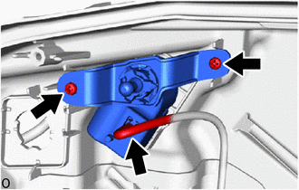
Remove the 2 screws.
-
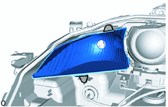
Hold the shaded areas shown in the illustration and remove the turn signal reflector.
Text in Illustration 
Hold Here -
Disconnect each connector.
Text in Illustration *A w/o AFS *B w/ AFS -
Using a vernier caliper, measure and record the protrusion amount of the vertical and horizontal aiming screw and vertical aiming screw.
Text in Illustration *A w/o AFS *B w/ AFS *a Protrusion Amount Measurement Area - - -
Loosen the vertical and horizontal aiming screw and vertical aiming screw 10 rotations.
-
Using a screwdriver, detach the 2 claws and disconnect the headlight unit LH from the pivot joint.
Tech Tips
Tape the screwdriver tip before use.
Text in Illustration *A w/o AFS *B w/ AFS Protective Tape - - -
While holding the headlight unit LH with one hand so that it does not fall over, loosen the vertical and horizontal aiming screw and vertical aiming screw until the headlight unit LH is removed.
Tech Tips
Count and record the number of rotations before the headlight unit LH is removed.
-
w/o AFS:
Remove the pivot joint.
Tech Tips
Install the removed pivot joint to the headlight unit LH.
-
Using a clip remover, remove the pivot joint.
Tech Tips
-
Tape the clip remover tip before use.
-
Install the removed pivot joint to the headlight unit LH.
Text in Illustration *A w/o AFS *B w/ AFS Protective Tape - - -
-
-
REMOVE HEADLIGHT LEVELING MOTOR (w/o AFS)
-
Disconnect the connector.
-
Remove the 2 screws.
-
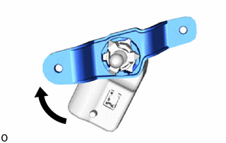
Turn the headlight leveling motor clockwise to remove it from the bracket.
-
-
REMOVE HEADLIGHT SWIVEL MOTOR LH (w/ AFS)
Note
-
Prevention of static electricity is required during this procedure.
-
Use static electricity countermeasures SST (desktop antistatic mat set) and observe all precautions to prevent damage to the system by electrostatic discharge (ESD).
-
Perform work using clean rubber gloves.
-
Do not touch the headlight unit assembly LH with bare hands.
-
Do not allow metallic surfaces to become dirty, as such surfaces become damaged even if they are only lightly wiped with a soft cloth.
-
Do not use solvent to clean components. Only clean them with a dry cloth.
- SST
- 09890-47010 ( 09891-04010, 09891-04020, 09891-04030, 09891-04040 )
-
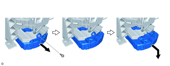
Remove the screw.
-
Slide the headlight swivel motor LH towards yourself and downward to remove it.
-