LIGHTING SYSTEM High Beam Headlight Circuit
DESCRIPTION
The headlight ECU sub-assembly controls the high beam headlights.
WIRING DIAGRAM
-
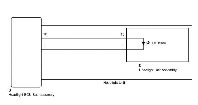
without AFS (Adaptive Front-lighting System)
-
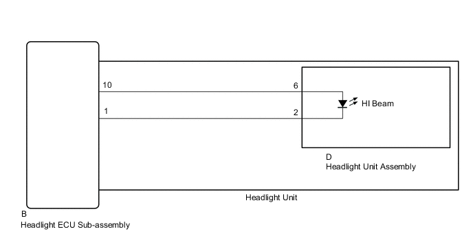
with AFS (Adaptive Front-lighting System)
CAUTION / NOTICE / HINT
Note
If the headlight ECU sub-assembly LH has been replaced, it is necessary to synchronize the vehicle information and initialize the headlight ECU sub-assembly LH Click here.
PROCEDURE
-
PERFORM ACTIVE TEST USING GTS
-
without AFS (Adaptive Front-lighting System):
-
Using the GTS, perform the Active Test Click here.
HL AutoLeveling Tester Display Test Part Control Range Diagnostic Note Headlight High Beam High beam headlights ON/OFF - OK High beam headlights illuminate.
-
-
with AFS (Adaptive Front-lighting System):
-
Using the GTS, perform the Active Test Click here.
AFS Tester Display Test Part Control Range Diagnostic Note Headlight High Beam High beam headlights ON/OFF -
Result Result Proceed to OK A NG (for LH Side) B NG (for RH Side) C -
A 
REPLACE HEADLIGHT ECU SUB-ASSEMBLY Click here
C 
INSPECT HEADLIGHT UNIT RH Click here
B 
-
-
INSPECT HEADLIGHT UNIT LH
-
Remove the headlight assembly LH Click here.
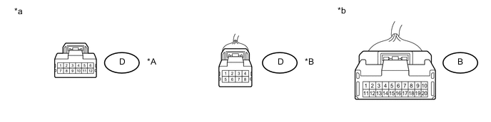
Text in Illustration *A without AFS (Adaptive Front-lighting System) *B with AFS (Adaptive Front-lighting System) *a Component without harness connected
(to Headlight Unit Assembly LH)
*b Component without harness connected
(to Headlight ECU Sub-assembly LH)
-
Remove the headlight unit LH Click here.
-
Measure the resistance according to the value(s) in the table below.
Standard Resistance without AFS (Adaptive Front-lighting System) Tester Connection Condition Specified Condition B-10 - D-10 Always Below 1 Ω B-1 - D-4 Always Below 1 Ω with AFS (Adaptive Front-lighting System) Tester Connection Condition Specified Condition B-10 - D-6 Always Below 1 Ω B-1 - D-2 Always Below 1 Ω
NG
REPLACE HEADLIGHT UNIT LH Click here
OK
-
-
CHECK HEADLIGHT UNIT ASSEMBLY LH
-
Replace the headlight unit LH with a new or known good one Click here.
-
Check that the high beam light LH operate normally.
OK High beam light LH operate normally.
OK
END (HEADLIGHT UNIT ASSEMBLY LH WAS DEFECTIVE)
NG
REPLACE HEADLIGHT ECU SUB-ASSEMBLY RH Click here
-
-
INSPECT HEADLIGHT UNIT RH
-
Remove the headlight assembly RH Click here.
Text in Illustration *A without AFS (Adaptive Front-lighting System) *B with AFS (Adaptive Front-lighting System) *a Component without harness connected
(to Headlight Unit Assembly RH)
*b Component without harness connected
(to Headlight ECU Sub-assembly RH)
-
Remove the headlight unit RH Click here.
-
Measure the resistance according to the value(s) in the table below.
Standard Resistance without AFS (Adaptive Front-lighting System) Tester Connection Condition Specified Condition B-10 - D-10 Always Below 1 Ω B-1 - D-4 Always Below 1 Ω with AFS (Adaptive Front-lighting System) Tester Connection Condition Specified Condition B-10 - D-6 Always Below 1 Ω B-1 - D-2 Always Below 1 Ω
NG
REPLACE HEADLIGHT UNIT RH Click here
OK
-
-
CHECK HEADLIGHT UNIT ASSEMBLY RH
-
Replace the headlight unit RH with a new or known good one Click here.
-
Check that the high beam light RH operate normally.
OK High beam light RH operate normally.
OK
END (HEADLIGHT UNIT ASSEMBLY RH WAS DEFECTIVE)
NG
REPLACE HEADLIGHT ECU SUB-ASSEMBLY Click here
-