LIGHTING SYSTEM Clearance Light/Daytime Running Light Circuit
DESCRIPTION
-
The clearance lights operate when the main body ECU (multiplex network body ECU) receives a light control switch position signal and sends an illumination command signal to the headlight ECU sub-assembly LH to illuminate the clearance/daytime running light LEDs.
Clearance light function:
-
The daytime running lights operate when the daytime running light operation conditions are met and the main body ECU (multiplex network body ECU) sends an illumination command signal to the headlight ECU sub-assembly LH so that the clearance/daytime running light LEDs illuminate at the daytime running light brightness level (a brightness level higher than the clearance lights).
Daytime running light function (w/ DRL OFF Switch):
WIRING DIAGRAM
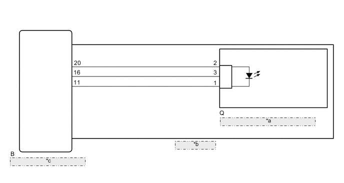
| *a | No.1 Headlight Clearance LED Unit |
| *b | Headlight Unit |
| *c | Headlight ECU Sub-assembly |
CAUTION / NOTICE / HINT
Note
-
Perform this inspection with the daytime running light function in the customization set to "ON" Click here.
-
If the headlight ECU sub-assembly LH has been replaced, it is necessary to synchronize the vehicle information and initialize the headlight ECU sub-assembly LH Click here.
PROCEDURE
-
PERFORM ACTIVE TEST USING GTS
-
*: w/ DRL OFF Switch
-
for Single Beam Headlight without AFS (Adaptive Front-lighting System):
-
Using the GTS, perform the Active Test Click here.
AFS Tester Display Test Part Control Range Diagnostic Note Clearance Light Clearance lights ON/OFF - Daytime Running Light* Daytime running lights ON/OFF - OK Clearance lights and daytime running lights illuminate.
-
-
for Triple Beam Headlight, for Single Beam Headlight with AFS (Adaptive Front-lighting System):
-
Using the GTS, perform the Active Test Click here.
AFS Tester Display Test Part Control Range Diagnostic Note Clearance Light Clearance lights ON/OFF - Daytime Running Light* Daytime running lights ON/OFF - OK Clearance lights and daytime running lights illuminate.
Result Result Proceed to OK A NG (for LH Side) B NG (for RH Side) C -
A 
REPLACE HEADLIGHT ECU SUB-ASSEMBLY LH Click here
C 
INSPECT HEADLIGHT UNIT RH Click here
B 
-
-
INSPECT HEADLIGHT UNIT LH
-
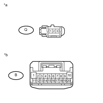
Text in Illustration *a Component without harness connected
(to No. 1 Headlight Clearance LED Unit LH)
*b Component without harness connected
(to Headlight ECU Sub-assembly LH)
Remove the headlight unit LH.
-
for Single Beam Headlight: Click here
-
for Triple Beam Headlight: Click here
-
-
Remove the No. 1 headlight clearance LED unit LH.
-
for Single Beam Headlight: Click here
-
for Triple Beam Headlight: Click here
-
-
Measure the resistance according to the value(s) in the table below.
Standard Resistance Tester Connection Condition Specified Condition B-20 - Q-2 Always Below 1 Ω B-16 - Q-3 Always Below 1 Ω B-11 - Q-1 Always Below 1 Ω Result Result Proceed to OK A NG (for Single Beam Headlight) B NG (for Triple Beam Headlight) C
B
REPLACE HEADLIGHT UNIT LH Click here
C
REPLACE HEADLIGHT UNIT LH Click here
A
-
-
CHECK NO. 1 HEADLIGHT CLEARANCE LED UNIT LH
-
Replace the No. 1 headlight clearance LED unit LH with a new or known good one.
-
for Single Beam Headlight: Click here
-
for Triple Beam Headlight: Click here
-
-
Check that the clearance light LH and daytime running light LH operate normally.
OK Clearance light LH and daytime running light LH operate normally.
OK
REPLACE HEADLIGHT ECU SUB-ASSEMBLY RH Click here
NG
REPLACE HEADLIGHT ECU SUB-ASSEMBLY LH Click here
-
-
INSPECT HEADLIGHT UNIT RH
-
Text in Illustration *a Component without harness connected
(to No. 1 Headlight Clearance LED Unit RH)
*b Component without harness connected
(to Headlight ECU Sub-assembly RH)
Remove the headlight unit RH.
-
for Single Beam Headlight: Click here
-
for Triple Beam Headlight: Click here
-
-
Remove the No. 1 headlight clearance LED unit RH.
-
for Single Beam Headlight: Click here
-
for Triple Beam Headlight: Click here
-
-
Measure the resistance according to the value(s) in the table below.
Standard Resistance Tester Connection Condition Specified Condition B-20 - Q-2 Always Below 1 Ω B-16 - Q-3 Always Below 1 Ω B-11 - Q-1 Always Below 1 Ω Result Result Proceed to OK A NG (for Single Beam Headlight) B NG (for Triple Beam Headlight) C
B
REPLACE HEADLIGHT UNIT RH Click here
C
REPLACE HEADLIGHT UNIT RH Click here
A
-
-
CHECK NO. 1 HEADLIGHT CLEARANCE LED UNIT RH
-
Replace the No. 1 headlight clearance LED unit RH with a new or known good one.
-
for Single Beam Headlight: Click here
-
for Triple Beam Headlight: Click here
-
-
Check that the clearance light RH and daytime running light RH operate normally.
OK Clearance light RH and daytime running light RH operate normally.
OK
END (NO. 1 HEADLIGHT CLEARANCE LED UNIT RH WAS DEFECTIVE)
NG
REPLACE HEADLIGHT ECU SUB-ASSEMBLY RH Click here
-