LIGHTING SYSTEM Turn Signal Switch Circuit
DESCRIPTION
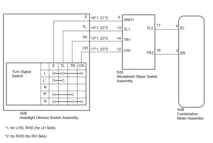
When the combination meter receives a signal from the windshield wiper switch, it turns the right and left turn signal lights on and off according to the operation of the headlight dimmer switch.
WIRING DIAGRAM
PROCEDURE
-
READ VALUE USING GTS (TURN SIGNAL SWITCH)
-
Using the GTS, read the Data List Click here.
Combination Meter Tester Display Measurement Item/Range Normal Condition Diagnostic Note Turn Signal Switch (Right) Turn signal switch (right turn position) signal / ON or OFF ON: Turn signal switch in right turn position
OFF: Turn signal switch not in right turn position
- Turn Signal Switch (Left) Turn signal switch (left turn position) signal / ON or OFF ON: Turn signal switch in left turn position
OFF: Turn signal switch not in left turn position
- OK The display is as specified in the normal condition column.
OK 
PROCEED TO NEXT SUSPECTED AREA SHOWN IN PROBLEM SYMPTOMS TABLE Click here
NG 
-
-
INSPECT HEADLIGHT DIMMER SWITCH ASSEMBLY
-
Remove the headlight dimmer switch Click here.
-
Inspect the headlight dimmer switch Click here.
NG
REPLACE HEADLIGHT DIMMER SWITCH ASSEMBLY Click here
OK
-
-
CHECK HARNESS AND CONNECTOR (HEADLIGHT DIMMER SWITCH - WINDSHIELD WIPER SWITCH)
-
Disconnect the N28 headlight dimmer switch connector.
-
Disconnect the N35 windshield wiper switch connector.
-
Measure the resistance according to the value(s) in the table below.
Standard Resistance for LHD, RHD (for LH Side) Tester Connection Condition Specified Condition N35-6 (GND1) - N28-16 (E) Always Below 1 Ω N35-13 (TL1) - N28-14 (TL) Always Below 1 Ω N35-14 (TR1) - N28-15 (TR) Always Below 1 Ω N35-12 (CR1) - N28-17 (CR) Always Below 1 Ω N35-6 (GND1) - Body ground Always 10 kΩ or higher N35-13 (TL1) - Body ground Always 10 kΩ or higher N35-14 (TR1) - Body ground Always 10 kΩ or higher N35-12 (CR1) - Body ground Always 10 kΩ or higher for RHD (for RH Side) Tester Connection Condition Specified Condition N35-6 (GND1) - N28-21 (E) Always Below 1 Ω N35-13 (TL1) - N28-22 (TL) Always Below 1 Ω N35-14 (TR1) - N28-23 (TR) Always Below 1 Ω N35-12 (CR1) - N28-20 (CR) Always Below 1 Ω N35-6 (GND1) - Body ground Always 10 kΩ or higher N35-13 (TL1) - Body ground Always 10 kΩ or higher N35-14 (TR1) - Body ground Always 10 kΩ or higher N35-12 (CR1) - Body ground Always 10 kΩ or higher
NG
REPAIR OR REPLACE HARNESS OR CONNECTOR
OK
-
-
CHECK HARNESS AND CONNECTOR (WINDSHIELD WIPER SWITCH - COMBINATION METER)
-
Disconnect the N35 windshield wiper switch connector.
-
Disconnect the N39 combination meter connector.
-
Measure the resistance according to the value(s) in the table below.
Standard Resistance Tester Connection Condition Specified Condition N35-17 (TL2) - N39-4 (EL) Always Below 1 Ω N35-16 (TR2) - N39-3 (ER) Always Below 1 Ω N35-17 (TL2) - Body ground Always 10 kΩ or higher N35-16 (TR2) - Body ground Always 10 kΩ or higher
NG
REPAIR OR REPLACE HARNESS OR CONNECTOR
OK
-
-
CHECK WINDSHIELD WIPER SWITCH ASSEMBLY
-
Replace the windshield wiper switch assembly with a new or known good one Click here.
-
Check that the turn signal switch.
OK Turn signal switch operate normally.
OK
END (WINDSHIELD WIPER SWITCH ASSEMBLY WAS DEFECTIVE)
NG
REPLACE COMBINATION METER ASSEMBLY Click here
-