HOOD LOCK CONTROL CABLE ASSEMBLY(for RHD) INSTALLATION
PROCEDURE
-
INSTALL HOOD LOCK CONTROL CABLE ASSEMBLY
-
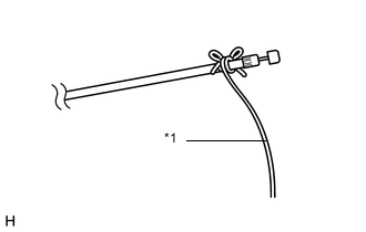
Text in Illustration *1 String Tie the string that was passed through the engine compartment to the end of the hood lock control cable assembly as shown in the illustration.
Tech Tips
Use a length of string long enough to pass through the engine compartment.
-
Pass the hood lock control cable assembly through the vehicle body, and then attach each clamp.
-
Untie the string from the hood lock control cable assembly.
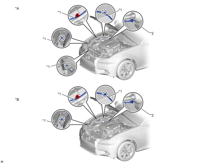
Text in Illustration *A w/o Cover *B w/ Cover *1 Hood Lock Control Cable *2 Stopper
-
-
INSTALL NO. 2 HOOD LOCK CONTROL CABLE COVER (w/ Cover)
-
Attach the claw to install the No. 2 hood lock control cable cover.
-
Install the screw.
-
-
INSTALL HOOD LOCK CONTROL CABLE COVER (w/ Cover)
-
Attach the guide to install the hood lock control cable cover.
-
-
INSTALL UPPER RADIATOR SUPPORT (w/ Cover)
-
Install the upper radiator support with the 5 bolts.
- Torque:
- 8.0 N*m { 82 kgf*cm, 71 in.*lbf }
-
Connect each connector.
-
Attach the 2 claws and install the 2 screws.
-
-
INSTALL NO. 1 INLET AIR CLEANER (w/ Cover)
-
INSTALL HOOD LOCK ASSEMBLY
-
Connect the hood lock control cable to the hood lock.
-
Install the hood lock with the 3 bolts.
- Torque:
- 7.5 N*m { 76 kgf*cm, 66 in.*lbf }
-
-
INSTALL HOOD LOCK RELEASE LEVER PROTECTOR
-
Install the hood lock release lever protector with the 2 clips.
-
Attach the 2 clamps and connect the connector.
-
-
INSTALL HOOD LOCK CONTROL LEVER SUB-ASSEMBLY
-
Connect the hood lock control cable to the hood lock control lever sub-assembly.
-
Attach the 3 claws to install the hood lock control lever sub-assembly.
-
-
INSTALL NO. 1 INSTRUMENT PANEL UNDER COVER SUB-ASSEMBLY
-
Connect the connectors and attach the clamp.
-
Attach the 2 claws to install the No. 1 instrument panel under cover sub-assembly.
-
Install the 3 screws.
-
-
INSTALL FRONT FENDER UPPER PROTECTOR RH
-
Attach the 3 clips to install the front fender upper protector RH.
-
-
INSTALL COOL AIR INTAKE DUCT SEAL
-
INSTALL ENGINE ROOM SIDE COVER