SLIDING ROOF SYSTEM Sliding Roof does not Move by Operating Sliding Roof Control Switch
DESCRIPTION
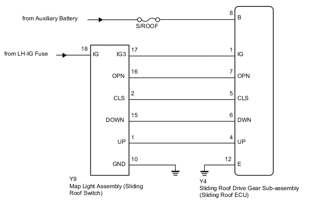
The sliding roof drive gear sub-assembly (sliding roof ECU) receives slide and tilt signals when the map light assembly (sliding roof switch) is operated and drives its built-in motor.
WIRING DIAGRAM
CAUTION / NOTICE / HINT
Note
-
Inspect the fuses for circuits related to this system before performing the following inspection procedure.
-
When the sliding roof drive gear sub-assembly (sliding roof ECU) is removed and reinstalled or replaced, the sliding roof drive gear sub-assembly (sliding roof ECU) must be initialized Click here.
-
Since the sliding roof system has functions that use LIN communication, first confirm that there is no malfunction in the LIN communication system with the How to Proceed with Troubleshooting procedure Click here.
PROCEDURE
-
READ VALUE USING GTS (SLIDING ROOF SWITCH)
-
Connect the GTS to the DLC3.
-
Turn the power switch on (IG).
-
Turn the GTS on.
-
Enter the following menus: Body Electrical / Sliding Roof / Data List.
-
Read the Data List according to the display on the GTS.
Sliding Roof (Sliding Roof Drive Gear Sub-assembly [Sliding Roof ECU]) Tester Display Measurement Item/Range Normal Condition Diagnostic Note Open Switch SLIDE OPEN switch signal / ON or OFF ON: SLIDE OPEN switch pressed
OFF: SLIDE OPEN switch not pressed
- Close Switch SLIDE CLOSE switch signal / ON or OFF ON: SLIDE CLOSE switch pressed
OFF: SLIDE CLOSE switch not pressed
- Up Switch TILT UP switch signal / ON or OFF ON: TILT UP switch pressed
OFF: TILT UP switch not pressed
- Down Switch TILT DOWN switch signal / ON or OFF ON: TILT DOWN switch pressed
OFF: TILT DOWN switch not pressed
- OK The GTS display changes according to switch operation as shown in the table.
NG 
INSPECT MAP LIGHT ASSEMBLY (SLIDING ROOF SWITCH) Click here
OK 
-
-
CHECK HARNESS AND CONNECTOR (SLIDING ROOF DRIVE GEAR SUB-ASSEMBLY - BATTERY AND BODY GROUND)
-
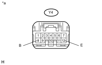
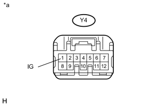
Text in Illustration *a Front view of harness connector
(to Sliding Roof Drive Gear Sub-assembly [Sliding Roof ECU])
Disconnect the sliding roof drive gear sub-assembly (sliding roof ECU) connector.
-
Measure the voltage according to the value(s) in the table below.
Standard Voltage Tester Connection Condition Specified Condition Y4-8 (B) - Body ground Always 11 to 14 V -
Measure the resistance according to the value(s) in the table below.
Standard Resistance Tester Connection Condition Specified Condition Y4-12 (E) - Body ground Always Below 1 Ω
OK 
REPLACE SLIDING ROOF DRIVE GEAR SUB-ASSEMBLY (SLIDING ROOF ECU) Click here
NG
REPAIR OR REPLACE HARNESS OR CONNECTOR
-
-
INSPECT MAP LIGHT ASSEMBLY (SLIDING ROOF SWITCH)
-
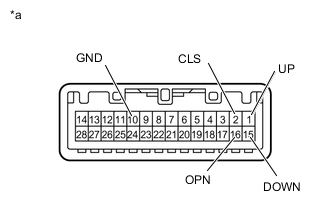
Text in Illustration *a Component without harness connected
(Sliding Roof Switch [Map Light Assembly])
Remove the map light assembly (sliding roof switch assembly) Click here.
-
Measure the resistance according to the value(s) in the table below.
Standard Resistance Tester Connection Switch Condition Specified Condition 15 (DOWN) - 10 (GND) TILT DOWN switch is pressed Below 1 Ω 15 (DOWN) - 10 (GND) TILT DOWN switch is not pressed 10 kΩ or higher 1 (UP) - 10 (GND) TILT UP switch is pressed Below 1 Ω 1 (UP) - 10 (GND) TILT UP switch is not pressed 10 kΩ or higher 2 (CLS) - 10 (GND) SLIDE CLOSE switch is pressed Below 1 Ω 2 (CLS) - 10 (GND) SLIDE CLOSE switch is not pressed 10 kΩ or higher 16 (OPN) - 10 (GND) SLIDE OPEN switch is pressed Below 1 Ω 16 (OPN) - 10 (GND) SLIDE OPEN switch is not pressed 10 kΩ or higher
NG
REPLACE MAP LIGHT ASSEMBLY (SLIDING ROOF SWITCH) Click here
OK
-
-
CHECK HARNESS AND CONNECTOR (SLIDING ROOF DRIVE GEAR SUB-ASSEMBLY - SLIDING ROOF SWITCH AND BODY GROUND)
-
Disconnect the Y4 sliding roof drive gear sub-assembly (sliding roof ECU) connector.
-
Disconnect the Y9 map light assembly (sliding roof switch) connector.
-
Measure the resistance according to the value(s) in the table below.
Standard Resistance Tester Connection Condition Specified Condition Y4-5 (CLS) - Y9-2 (CLS) Always Below 1 Ω Y4-5 (CLS) - Body ground Always 10 kΩ or higher Y4-7 (OPN) - Y9-16 (OPN) Always Below 1 Ω Y4-7 (OPN) - Body ground Always 10 kΩ or higher Y4-6 (DWN) - Y9-15 (DOWN) Always Below 1 Ω Y4-6 (DWN) - Body ground Always 10 kΩ or higher Y4-4 (UP) - Y9-1 (UP) Always Below 1 Ω Y4-4 (UP) - Body ground Always 10 kΩ or higher Y4-1 (IG) - Y9-17 (IG3) Always Below 1 Ω Y4-1 (IG) - Body ground Always 10 kΩ or higher Y9-10 (GND) - Body ground Always Below 1 Ω
NG
REPAIR OR REPLACE HARNESS OR CONNECTOR
OK
-
-
CHECK HARNESS AND CONNECTOR (MAP LIGHT ASSEMBLY - BATTERY AND BODY GROUND)
-
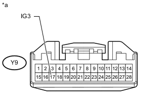
Text in Illustration *a Front view of harness connector
(to Map Light Assembly [Sliding Roof Switch])
Disconnect the map light assembly (sliding roof switch) connector.
-
Measure the voltage according to the value(s) in the table below.
Standard Voltage Tester Connection Switch Condition Specified Condition Y9-17 (IG3) - Body ground Power switch on (IG) 11 to 14 V
NG
REPAIR OR REPLACE HARNESS OR CONNECTOR
OK
-
-
CHECK HARNESS AND CONNECTOR (SLIDING ROOF DRIVE GEAR SUB-ASSEMBLY - BATTERY AND BODY GROUND)
-
Text in Illustration *a Front view of harness connector
(to Sliding Roof Drive Gear Sub-assembly [Sliding Roof ECU])
Disconnect the sliding roof drive gear sub-assembly (sliding roof ECU) connector.
-
Measure the voltage according to the value(s) in the table below.
Standard Voltage Tester Connection Switch Condition Specified Condition Y4-1 (IG) - Body ground Power switch on (IG) 11 to 14 V
OK
REPLACE SLIDING ROOF DRIVE GEAR SUB-ASSEMBLY (SLIDING ROOF ECU) Click here
NG
REPLACE MAP LIGHT ASSEMBLY (SLIDING ROOF SWITCH) Click here
-