ROOF HEADLINING REASSEMBLY
CAUTION / NOTICE / HINT
Tech Tips
-
Use the same procedure for RHD and LHD vehicles.
-
The procedure listed below is for LHD vehicles.
PROCEDURE
-
INSTALL NO. 1 ROOF WIRE
-
w/ Sliding Roof:
-
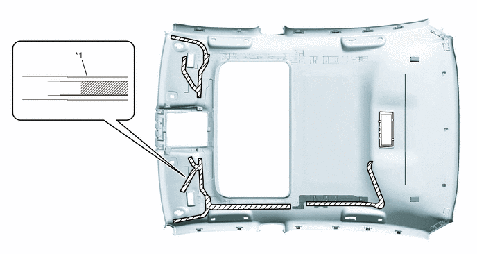
Apply butyl tape as shown in the illustration.
Tech Tips
Place the tape securely so that it is not misaligned or peeling.
-
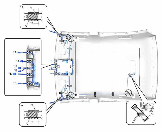
Align the positioning tape of the No. 1 roof wire with the protrusion of the roof headlining and wrap tape around them as shown in the part of the illustration labeled A.
-
Attach the No. 1 roof wire to the butyl tape.
Tech Tips
-
Adjust the slack of the No. 1 roof wire in the parts of the illustration labeled B and apply tape.
-
Make sure that the No. 1 roof wire is securely attached to the roof headlining along its entire length and that it is not twisted.
-
-
Attach the clamps.
-
Apply tape to the marked areas to fix the No. 1 roof wire in place.
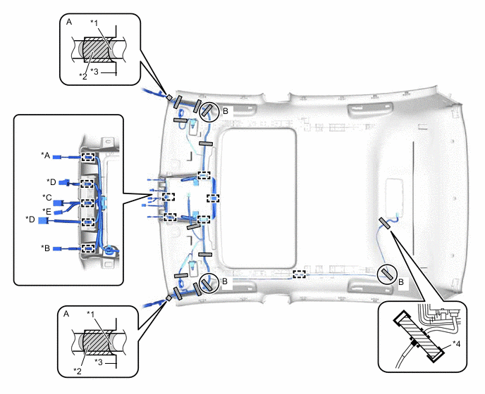
Text in Illustration *A w/ Rain Sensor, for LHD *B w/ Rain Sensor, for RHD *C w/o Pre-crash Safety System *D w/ Pre-crash Safety System *E w/ Camera Heater - - *1 No. 1 Roof Wire Positioning Tape *2 Tape *3 Roof Headlining *4 Marking 
Fastening Tape - - -
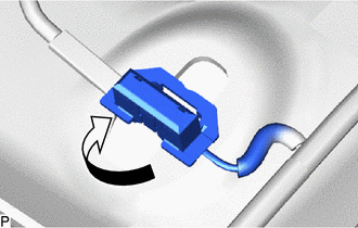
Text in Illustration *1 Marking - - Butyl Tape - - Turn the visor connectors approximately 90° clockwise to install them to the roof headlining.
-
-
w/o Sliding Roof:
-
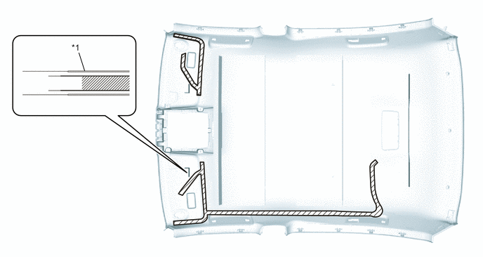
Apply butyl tape as shown in the illustration.
Tech Tips
Place the tape securely so that it is not misaligned or peeling.
-
Align the positioning tape of the No. 1 roof wire with the protrusion of the roof headlining and wrap tape around them as shown in the part of the illustration labeled A.
-
Attach the No. 1 roof wire to the butyl tape.
Tech Tips
-
Adjust the slack of the No. 1 roof wire in the parts of the illustration labeled B and apply tape.
-
Make sure that the No. 1 roof wire is securely attached to the roof headlining along its entire length and that it is not twisted.
-
-
Attach the clamps.
-
Apply tape to the marked areas to fix the No. 1 roof wire in place.
Text in Illustration *A w/ Rain Sensor, for LHD *B w/ Rain Sensor, for RHD *C w/o Pre-crash Safety System *D w/ Pre-crash Safety System *E w/ Camera Heater - - *1 No. 1 Roof Wire Positioning Tape *2 Tape *3 Roof Headlining *4 Marking Fastening Tape - - -
Text in Illustration *1 Marking - - Butyl Tape - - Turn the visor connectors approximately 90° clockwise to install them to the roof headlining.
-
-
-
INSTALL VANITY LIGHT ASSEMBLY
Tech Tips
Use the same procedure for both vanity light assemblies.
-
Attach the 3 claws to install the vanity light assembly.
-