ROOF HEADLINING REMOVAL
CAUTION / NOTICE / HINT
Tech Tips
-
Use the same procedure for RHD and LHD vehicles.
-
The procedure listed below is for LHD vehicles.
PROCEDURE
-
DISABLE AUTO TILT AWAY FUNCTION
-
Disable the autoaway/return function by changing the customize parameter Click here.
CAUTION:
Record the current customize parameter setting (whether the autoaway/return function is enabled or disabled) in order to restore the current setting after finishing the operation.
Tech Tips
Performing the above operation causes the autoaway/return function to be disabled when the power switch is turned off.
-
Turn the power switch on (IG). Operate the tilt and telescopic switch to fully extend and lower the steering column assembly.
-
Turn the power switch off.
-
-
REMOVE LUGGAGE COMPARTMENT FLOOR MAT
-
REMOVE LUGGAGE COMPARTMENT TRIM COVER LH
-
PRECAUTION
Note
After turning the power switch off, waiting time may be required before disconnecting the cable from the auxiliary battery terminal. Therefore, make sure to read the disconnecting the cable from the auxiliary battery terminal notice before proceeding with work Click here.
-
DISCONNECT CABLE FROM NEGATIVE AUXILIARY BATTERY TERMINAL
CAUTION:
Wait at least 90 seconds after disconnecting the cable from the negative (-) auxiliary battery terminal to disable the SRS system.
Note
When disconnecting the cable, some systems need to be initialized after the cable is reconnected Click here.
-
REMOVE FRONT SEAT ASSEMBLY LH
-
for Sports Seat Type:
-
for Luxury Seat Type:
-
for Standard Seat Type:
-
-
REMOVE FRONT SEAT ASSEMBLY RH
Tech Tips
Use the same procedure described for the LH side.
-
REMOVE REAR SEAT ASSEMBLY
-
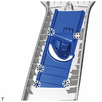
REMOVE FRONT DOOR SCUFF PLATE LH
-
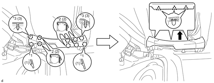
Place your hands on the inner portion of the front door scuff plate LH and detach the 2 claws labeled A, 6 claws labeled B and 2 claws labeled C in the order shown in the illustration.
-
Raise the front door scuff plate LH to detach the 4 clips on the outer side and remove it.
Text in Illustration *1 Claw A *2 Claw B *3 Claw C - -
-
-
REMOVE FRONT DOOR SCUFF PLATE RH
Tech Tips
Use the same procedure described for the LH side.
-
REMOVE FRONT DOOR OPENING TRIM COVER LH
-
Detach the 5 claws and remove the front door opening trim cover LH.
-
-
REMOVE FRONT DOOR OPENING TRIM COVER RH
Tech Tips
Use the same procedure described for the LH side.
-
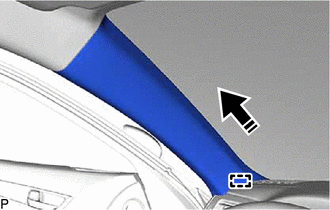
REMOVE FRONT PILLAR GARNISH LH
-
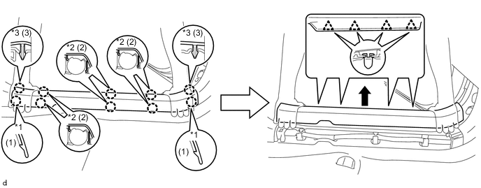
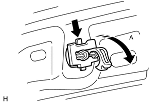
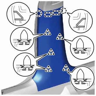
Pull up the front pillar garnish LH to detach the front pillar garnish clip A and front pillar garnish clip B as shown in the illustration.
Tech Tips
Make the front pillar garnish assembly LH hang down from the front pillar garnish clip A and front pillar garnish clip B.
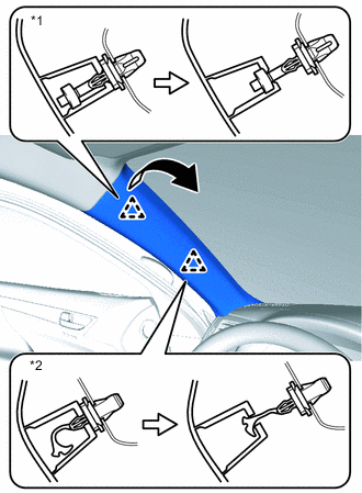
Text in Illustration *1 Front Pillar Garnish Clip A *2 Front Pillar Garnish Clip B -
Using your fingers, grasp the parts indicated by the arrows shown in the illustration and remove the front pillar garnish clip A.
Note
If the front pillar garnish clip A is damaged, replace it with a new one.
-
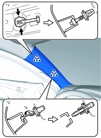
Turn the end of the front pillar garnish clip B 90° with needle-nose pliers and remove it from the front pillar garnish LH.
Note
If the front pillar garnish clip B is damaged, replace it with a new one.
Text in Illustration *1 Front Pillar Garnish Clip A *2 Front Pillar Garnish Clip B *a 90° -
When the front pillar garnish clip A cannot be removed by using your fingers:
-
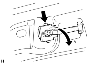
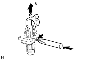
While pressing the part indicated by the arrow shown in the illustration with your finger, lift the front pillar garnish clip A in direction A.
-
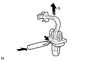
While pulling in direction B, push the part indicated by the arrow shown in the illustration with the end of a screwdriver to remove the front pillar garnish clip A.
Note
If the front pillar garnish clip A is damaged, replace it with a new one.
-
-
Detach the guide and remove the front pillar garnish LH.
-
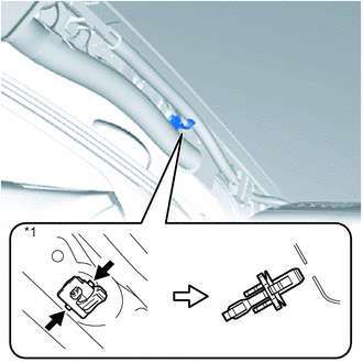
Text in Illustration *1 Front Pillar Garnish Clip B Using your fingers, grasp the parts indicated by the arrows shown in the illustration and remove the front pillar garnish clip B.
-
When the front pillar garnish clip B cannot be removed by using your fingers:
-
While pressing the part indicated by the arrow shown in the illustration with your finger, lift the front pillar garnish clip B in direction B.
-
While pulling in direction B, push the part indicated by the arrow shown in the illustration with the end of a screwdriver to remove the front pillar garnish clip B.
Note
If the front pillar garnish clip B is damaged, replace it with a new one.
-
-
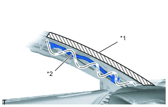
Text in Illustration *1 Adhesive Tape *2 Protective Cover Protect the curtain shield airbag assembly.
-
Completely cover the airbag with a cloth or nylon sheet and secure the ends of the cover with adhesive tape as shown in the illustration.
Note
Cover the curtain shield airbag with a protective cover as soon as the front pillar garnish is removed.
-
-
-
REMOVE FRONT PILLAR GARNISH RH
Tech Tips
Use the same procedure described for the LH side.
-
REMOVE CONSOLE BOX ASSEMBLY
-
REMOVE INSTRUMENT PANEL SAFETY PAD SUB-ASSEMBLY
-
REMOVE REAR DOOR SCUFF PLATE LH
-
Place your hands on the inner portion of the rear door scuff plate LH and detach the 2 claws labeled A, 6 claws labeled B and 2 claws labeled C in the order shown in the illustration.
-
Raise the rear door scuff plate LH to detach the 4 clips on the outer side and remove it.
Text in Illustration *1 Claw A *2 Claw B *3 Claw C - -
-
-
REMOVE REAR DOOR SCUFF PLATE RH
Tech Tips
Use the same procedure described for the LH side.
-
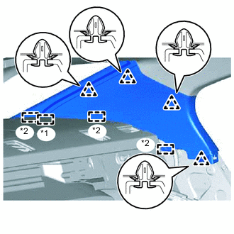
REMOVE LOWER CENTER PILLAR GARNISH LH
-
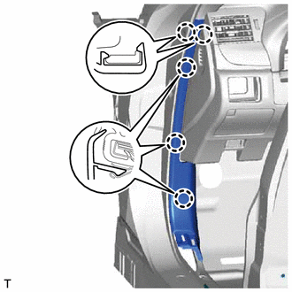
Pull both sides of the lower center pillar garnish LH outward to detach the 2 claws.
-
Detach the 5 clips and 2 guides and remove the lower center pillar garnish LH.
-
-
REMOVE LOWER CENTER PILLAR GARNISH RH
Tech Tips
Use the same procedure described for the LH side.
-
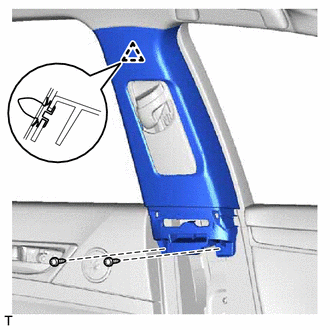
REMOVE UPPER CENTER PILLAR GARNISH LH
-
Remove the 2 screws.
-
Detach the clip.
-
Pass the front seat outer belt floor anchor through the center pillar garnish, and remove the center pillar garnish LH.
-
-
REMOVE UPPER CENTER PILLAR GARNISH RH
Tech Tips
Use the same procedure described for the LH side.
-
REMOVE REAR SEAT SIDE GARNISH LH
-
Detach the 4 claws and guide and remove the rear seat side garnish LH.
-
-
REMOVE REAR SEAT SIDE GARNISH RH
Tech Tips
Use the same procedure described for the LH side.
-
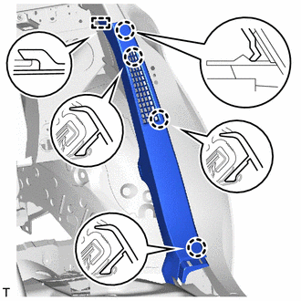
REMOVE INNER ROOF SIDE GARNISH LH
-
w/ Rear Sunshade:
-
Text in Illustration *1 End Of The Rear Window Shade Assembly *2 Guide Detach the 4 clips.
-
Detach the 3 guides and the end of the rear window shade assembly, and then remove the inner roof side garnish LH.
-
-
w/o Rear Sunshade:
-
Detach the 4 clips and 3 guides and remove the inner roof side garnish LH.
-
-
-
REMOVE INNER ROOF SIDE GARNISH RH
Tech Tips
Use the same procedure described for the LH side.
-
REMOVE MAP LIGHT ASSEMBLY
-
REMOVE SPOT LIGHT ASSEMBLY
-
REMOVE RAIN SENSOR COVER (w/ Rain Sensor)
-
REMOVE INNER REAR VIEW MIRROR STAY HOLDER COVER (w/o Pre-crash Safety System)
-
REMOVE NO. 2 FORWARD RECOGNITION COVER (w/ Pre-crash Safety System)
-
REMOVE NO. 1 FORWARD RECOGNITION COVER (w/ Pre-crash Safety System)
-
REMOVE VISOR BRACKET COVER
Tech Tips
Use the same procedure for both visor bracket covers.
-
Text in Illustration *1 Protective Tape Using a screwdriver, detach the 4 claws and remove the visor bracket cover.
-
-
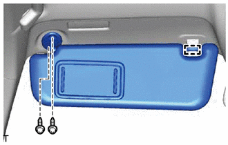
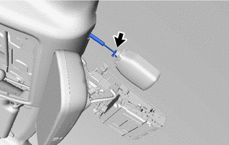
REMOVE VISOR ASSEMBLY LH
-
Detach the guide.
-
Remove the 2 screws and visor assembly LH.
-
-
REMOVE VISOR ASSEMBLY RH
Tech Tips
Use the same procedure described for the LH side.
-
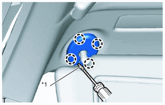
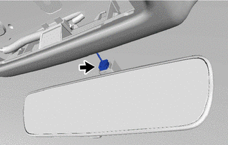
REMOVE VISOR HOLDER
Tech Tips
Use the same procedure for both visor holders.
-
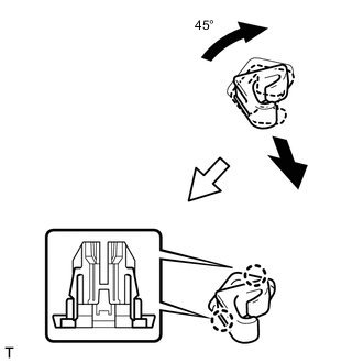
Turn the visor holder clockwise approximately 45° and pull it out as shown in the illustration.
-
Detach the 2 claws and remove the visor holder.
-
-
REMOVE ASSIST GRIP SUB-ASSEMBLY
Tech Tips
Use the same procedure for both assist grip sub-assemblies.
-
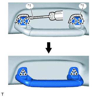
Text in Illustration *1 Protective Tape Put protective tape around the assist grip covers.
-
Using a screwdriver, detach the 4 claws and remove the 2 assist grip covers.
-
Detach the 2 clips and remove the assist grip sub-assembly.
-
Remove the 2 clips from the vehicle body.
-
-
REMOVE REAR ASSIST GRIP ASSEMBLY LH
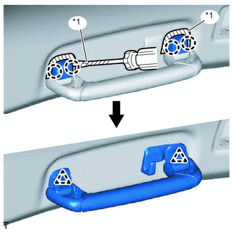
Text in Illustration *1 Protective Tape
-
Put protective tape around the assist grip covers.
-
Using a screwdriver, detach the 4 claws and remove the 2 assist grip covers.
-
Detach the 2 clips and remove the rear assist grip assembly LH.
-
Remove the 2 clips from the vehicle body.
-
-
REMOVE REAR ASSIST GRIP ASSEMBLY RH
Tech Tips
Use the same procedure described for the LH side.
-
REMOVE ROOF HEADLINING ASSEMBLY
-
w/ Rain Sensor:
-
Disconnect the connector.
-
-
w/o Pre-crash Safety System:
-
Disconnect the connector.
-
-
w/ Pre-crash Safety System:
-
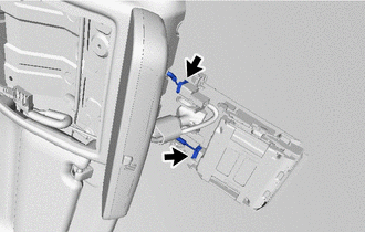
Disconnect the connectors.
-
-
w/ Camera Heater:
-
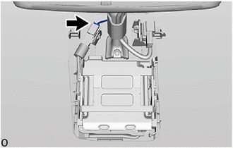
Disconnect the connector.
-
-
w/ Sliding Roof:
-
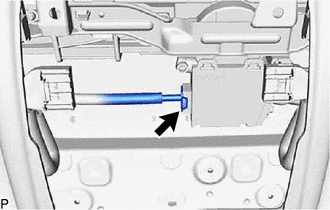
Disconnect the connector.
-
-
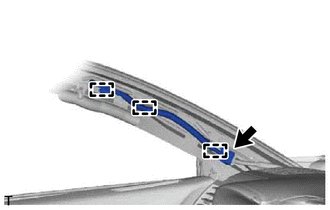
Disconnect the connector and detach the 3 clamps from the front pillar LH.
-
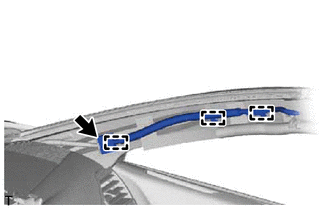
Disconnect the connector and detach the 3 clamps from the front pillar RH.
-
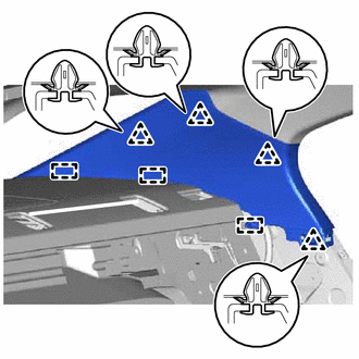
w/ Sliding Roof:
-
Detach the 10 fasteners and 15 clips.
-
Detach the guide.
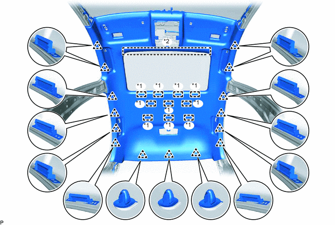
Text in Illustration *1 Fastener *2 Guide
-
-
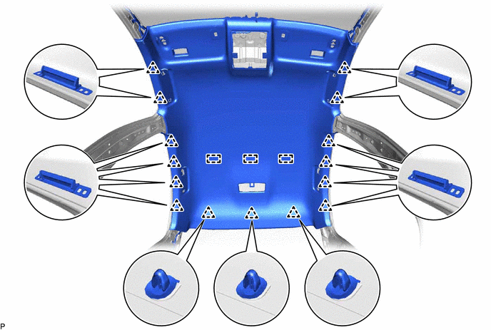
w/o Sliding Roof:
-
Detach the 3 fasteners and 15 clips.
-
-
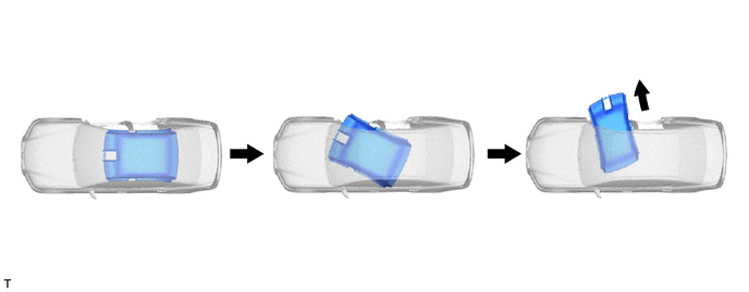
Move the roof headlining assembly as shown in the illustration and remove it from the right front door.
Note
-
Make sure that the roof headlining assembly does not get caught on anything as it may become bent or damaged.
-
Do not damage the roof headlining assembly or vehicle interior.
-
-
-
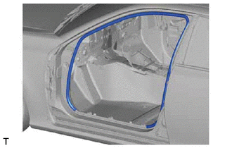
REMOVE FRONT DOOR OPENING TRIM WEATHERSTRIP LH
-
Remove the front door opening trim weatherstrip LH.
Tech Tips
Remove any remaining sealer from the vehicle body.
-
-
REMOVE FRONT DOOR OPENING TRIM WEATHERSTRIP RH
Tech Tips
Use the same procedure described for the LH side.
-
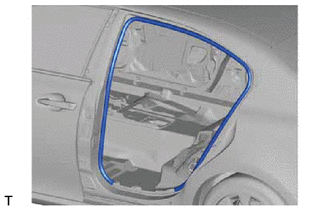
REMOVE REAR DOOR OPENING TRIM WEATHERSTRIP LH
-
Remove the rear door opening trim weatherstrip LH.
Tech Tips
Remove any remaining sealer from the vehicle body.
-
-
REMOVE REAR DOOR OPENING TRIM WEATHERSTRIP RH
Tech Tips
Use the same procedure described for the LH side.
-
REMOVE FRONT SHOULDER BELT ANCHOR PLATE SUB-ASSEMBLY LH
-
Detach the 4 claws and guide and remove the front shoulder belt anchor plate sub-assembly LH.
-
-
REMOVE FRONT SHOULDER BELT ANCHOR PLATE SUB-ASSEMBLY RH
Tech Tips
Use the same procedure described for the LH side.