INSTRUMENT PANEL SAFETY PAD REMOVAL
CAUTION / NOTICE / HINT
Tech Tips
-
Use the same procedure for RHD and LHD vehicles.
-
The procedure listed below is for LHD vehicles.
PROCEDURE
-
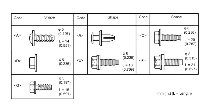
TABLE OF BOLT, SCREW AND NUT
Tech Tips
All bolts, screws, nuts and clips relevant to installing and removing the instrument panel are shown along with their alphabet code in the table below.
-
DISABLE AUTO TILT AWAY FUNCTION
-
Disable the autoaway/return function by changing the customize parameter Click here.
CAUTION:
Record the current customize parameter setting (whether the autoaway/return function is enabled or disabled) in order to restore the current setting after finishing the operation.
Tech Tips
Performing the above operation causes the autoaway/return function to be disabled when the power switch is turned off.
-
Turn the power switch on (IG). Operate the tilt and telescopic switch to fully extend and lower the steering column assembly.
-
Turn the power switch off.
-
-
REMOVE LUGGAGE COMPARTMENT FLOOR MAT
-
REMOVE LUGGAGE COMPARTMENT TRIM COVER LH
-
PRECAUTION
Note
After turning the power switch off, waiting time may be required before disconnecting the cable from the auxiliary battery terminal. Therefore, make sure to read the disconnecting the cable from the auxiliary battery terminal notice before proceeding with work Click here.
-
DISCONNECT CABLE FROM NEGATIVE AUXILIARY BATTERY TERMINAL
CAUTION:
Wait at least 90 seconds after disconnecting the cable from the negative (-) auxiliary battery terminal to disable the SRS system.
Note
When disconnecting the cable, some systems need to be initialized after the cable is reconnected Click here.
-
REMOVE CONSOLE BOX ASSEMBLY
-
REMOVE FRONT DOOR SCUFF PLATE LH
-
REMOVE FRONT DOOR SCUFF PLATE RH
-
REMOVE FRONT DOOR OPENING TRIM COVER LH
-
REMOVE FRONT DOOR OPENING TRIM COVER RH
-
REMOVE FRONT PILLAR GARNISH LH
-
REMOVE FRONT PILLAR GARNISH RH
-
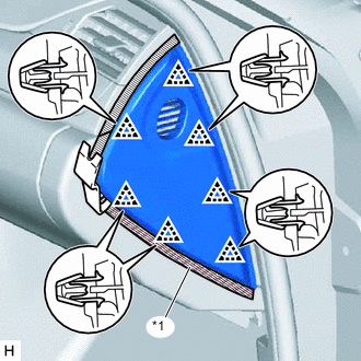
REMOVE INSTRUMENT SIDE PANEL LH
Text in Illustration *1 Protective Tape
-
Put protective tape around the instrument side panel LH.
-
Using moulding remover B, detach the 7 clips and remove the instrument side panel LH.
-
-
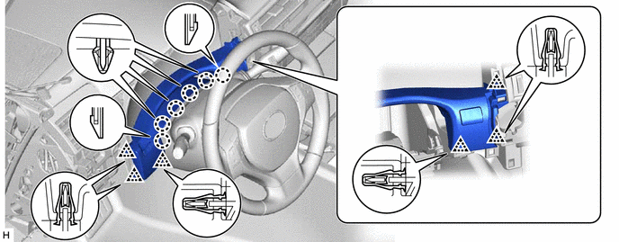
REMOVE NO. 1 INSTRUMENT PANEL GARNISH SUB-ASSEMBLY
Text in Illustration *1 Protective Tape
-
Put protective tape around the No. 1 instrument panel garnish sub-assembly.
-
Using moulding remover B, detach the 4 clips and remove the No. 1 instrument panel garnish sub-assembly.
-
-
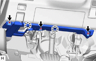
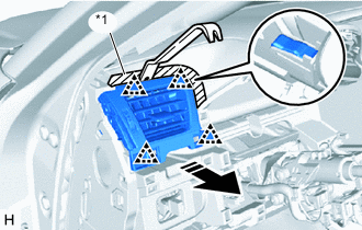
REMOVE NO. 1 INSTRUMENT PANEL UNDER COVER SUB-ASSEMBLY
-
Remove the 3 screws <A>.
-
Detach the 2 claws.
-
Disconnect the connectors, detach the clamp and remove the No. 1 instrument panel under cover sub-assembly.
-
-
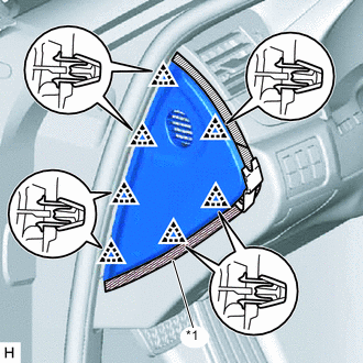
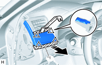
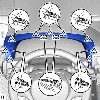
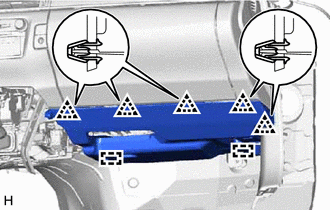
REMOVE NO. 1 INSTRUMENT PANEL SAFETY PAD SUB-ASSEMBLY

-
Detach the 9 clips and guide.
-
Disconnect the connectors and remove the No. 1 instrument panel safety pad sub-assembly.
-
-
REMOVE LOWER NO. 1 INSTRUMENT PANEL AIRBAG ASSEMBLY
-
REMOVE INSTRUMENT CLUSTER FINISH PANEL ASSEMBLY
-
Detach the 9 clips and 2 guides and remove the instrument cluster finish panel assembly.
-
-
REMOVE INSTRUMENT CLUSTER FINISH PANEL SUB-ASSEMBLY
-
Detach the 6 clips and 6 claws.
-
Disconnect the connectors and remove the instrument cluster finish panel sub-assembly.
-
-
REMOVE HEADLIGHT DIMMER SWITCH ASSEMBLY
-
REMOVE COMBINATION METER ASSEMBLY
-
REMOVE NO. 1 INSTRUMENT PANEL REGISTER ASSEMBLY
Text in Illustration *1 Protective Tape
-
Put protective tape around the No. 1 instrument panel register assembly.
-
Using moulding remover B, detach the 4 clips.
-
Disconnect the connector and remove the No. 1 instrument panel register assembly.
-
-
REMOVE INSTRUMENT SIDE PANEL RH
Text in Illustration *1 Protective Tape
-
Put protective tape around the instrument side panel RH.
-
Using moulding remover B, detach the 7 clips and remove the instrument side panel RH.
-
w/ Airbag Cut Off Switch:
-
Disconnect the connector.
-
-
-
REMOVE NO. 2 INSTRUMENT PANEL UNDER COVER SUB-ASSEMBLY
-
Detach the 5 clips and 2 guides.
-
Disconnect the connectors, detach the clamp and remove the No. 2 instrument panel under cover sub-assembly.
-
-
REMOVE GLOVE COMPARTMENT DOOR ASSEMBLY
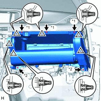
Text in Illustration *1 Screw <A> *2 Bolt <E>
-
Remove the 3 screws <A> and 2 bolts <E>.
-
Detach the 6 clips.
-
Disconnect the connectors, detach the clamp and remove the glove compartment door assembly.
-
-
REMOVE MULTI-MEDIA MODULE RECEIVER ASSEMBLY
-
REMOVE NO. 2 INSTRUMENT PANEL REGISTER ASSEMBLY
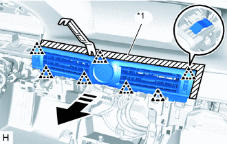
Text in Illustration *1 Protective Tape
-
Put protective tape around the No. 2 instrument panel register assembly.
-
Using moulding remover B, detach the 7 clips.
-
Disconnect the connectors and remove the No. 2 instrument panel register assembly.
-
-
REMOVE TELEMATICS TRANSCEIVER (w/ Telematics Transceiver)
-
REMOVE NO. 2 INSTRUMENT PANEL GARNISH SUB-ASSEMBLY

Text in Illustration *1 Protective Tape
-
Put protective tape around the No. 2 instrument panel garnish sub-assembly.
-
Remove the 2 screws <G> from the back of the No. 2 instrument panel garnish sub-assembly.
-
Using moulding remover B, detach the 9 clips and claw and remove the No. 2 instrument panel garnish sub-assembly together with the No. 3 instrument panel register assembly.
-
-
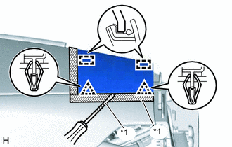
REMOVE NO. 1 INSTRUMENT PANEL SPEAKER PANEL SUB-ASSEMBLY
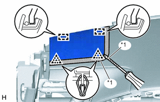
Text in Illustration *1 Protective Tape
-
Put protective tape around the No. 1 instrument panel speaker panel sub-assembly.
-
Using a screwdriver, detach the 2 clips and 2 guides and remove the No. 1 instrument panel speaker panel sub-assembly.
Tech Tips
Tape the screwdriver tip before use.
-
-
REMOVE NO. 2 INSTRUMENT PANEL SPEAKER PANEL SUB-ASSEMBLY
Text in Illustration *1 Protective Tape
-
Put protective tape around the No. 2 instrument panel speaker panel sub-assembly.
-
Using a screwdriver, detach the 2 clips and 2 guides and remove the No. 2 instrument panel speaker panel sub-assembly.
Tech Tips
Tape the screwdriver tip before use.
-
-
REMOVE FRONT NO. 2 SPEAKER ASSEMBLY
-
REMOVE NO. 1 SPEAKER OPENING COVER ASSEMBLY
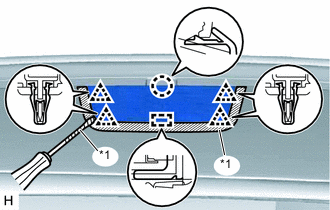
Text in Illustration *1 Protective Tape
-
Put protective tape around the No. 1 speaker opening cover assembly.
-
Using a screwdriver, detach the claw, 4 clips and guide and remove the No. 1 speaker opening cover assembly.
Tech Tips
Tape the screwdriver tip before use.
-
-
REMOVE FRONT NO. 3 SPEAKER ASSEMBLY
-
REMOVE UPPER INSTRUMENT CLUSTER FINISH PANEL
-
Put protective tape around the upper instrument cluster finish panel.
-
Remove the 3 clips <B>.
-
Detach the 2 clips and 3 claws and remove the upper instrument cluster finish panel.
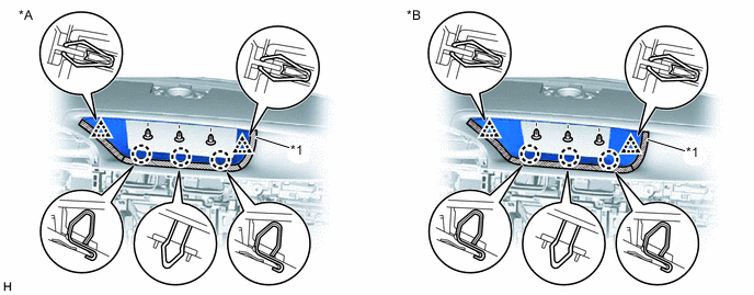
Text in Illustration *A for 12.3 Inch *B for 8 Inch *1 Protective Tape - -
-
-
REMOVE ACCESSORY METER ASSEMBLY (for 12.3 Inch)
-
REMOVE MULTI-DISPLAY (for 8 Inch)
-
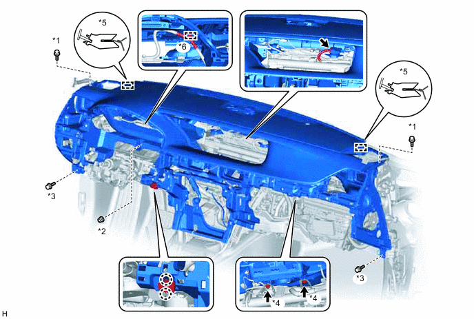
REMOVE INSTRUMENT PANEL SAFETY PAD SUB-ASSEMBLY
-
w/ Headup Display:
-
Disconnect the connectors and detach the clamp.
-
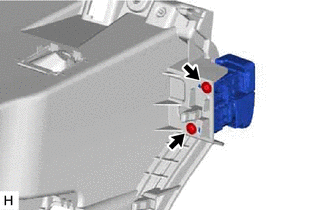
Detach the 2 claws and disconnect the room temperature sensor.
-
Remove the 2 bolts <C>, nut <D> and 2 bolts <E>.
-
Remove the 2 passenger airbag bolts <F>.
-
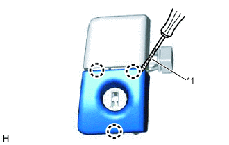
Detach the 2 guides and remove the instrument panel safety pad sub-assembly.
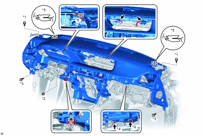
Text in Illustration *1 Bolt <C> *2 Nut <D> *3 Bolt <E> *4 Bolt <F> *5 Guide *6 Clamp
-
-
w/o Headup Display:
-
Disconnect the connectors and detach the clamp.
-
Detach the 2 claws and disconnect the room temperature sensor.
-
Remove the 2 bolts <C>, nut <D> and 2 bolts <E>.
-
Remove the 2 passenger airbag bolts <F>.
-
Detach the 2 guides and remove the instrument panel safety pad sub-assembly.
Text in Illustration *1 Bolt <C> *2 Nut <D> *3 Bolt <E> *4 Bolt <F> *5 Guide *6 Clamp
-
-
-
REMOVE GLOVE COMPARTMENT DOOR LOCK ASSEMBLY
-
Remove the 2 screws <A> and glove compartment door lock assembly.
-
-
REMOVE GLOVE COMPARTMENT DOOR LOCK COVER
Text in Illustration *1 Protective Tape
-
Using a screwdriver, detach the 3 claws and remove the glove compartment door lock cover.
Tech Tips
Tape the screwdriver tip before use.
-