AIR CONDITIONING UNIT REMOVAL
CAUTION / NOTICE / HINT
Tech Tips
-
Use the same procedure for RHD and LHD vehicles.
-
The procedure listed below is for LHD vehicles.
-
If the air conditioning radiator damper servo sub-assembly is to be removed and installed or replaced, make sure to set the temperature setting to MAX COLD before turning the power switch off and disconnecting the cable from the negative (-) auxiliary battery terminal.
PROCEDURE
-
REMOVE ENGINE ROOM SIDE COVER
-
REMOVE COOL AIR INTAKE DUCT SEAL
-
RECOVER REFRIGERANT FROM REFRIGERATION SYSTEM
-
for HFC-134a(R134a):
-
for HFO-1234yf(R1234yf):
-
-
REMOVE V-BANK COVER SUB-ASSEMBLY (for 2GR-FXE)
-
REMOVE NO. 1 ENGINE COVER (for 2AR-FSE)
-
REMOVE NO. 1 AIR CLEANER INLET
-
REMOVE AIR CLEANER CAP WITH AIR CLEANER HOSE (for 2GR-FXE)
-
REMOVE ENGINE UNDER COVER
-
DRAIN ENGINE COOLANT
-
for 2AR-FSE:
-
for 2GR-FXE:
-
-
PRECAUTION
Note
After turning the power switch off, waiting time may be required before disconnecting the cable from the auxiliary battery terminal. Therefore, make sure to read the disconnecting the cable from the auxiliary battery terminal notice before proceeding with work Click here.
-
REMOVE LUGGAGE COMPARTMENT FLOOR MAT
-
REMOVE LUGGAGE COMPARTMENT TRIM COVER LH
-
DISCONNECT CABLE FROM NEGATIVE AUXILIARY BATTERY TERMINAL
CAUTION:
Wait at least 90 seconds after disconnecting the cable from the negative (-) auxiliary battery terminal to disable the SRS system.
Note
When disconnecting the cable, some systems need to be initialized after the cable is reconnected Click here.
-
REMOVE FRONT WIPER MOTOR
-
DISCONNECT AIR CONDITIONING TUBE ASSEMBLY
-
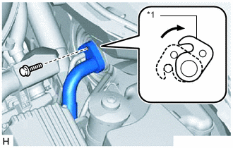
Text in Illustration *1 Plate Remove the bolt.
-
Detach the plate as shown in the illustration.
-
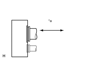
Text in Illustration *a Disconnect tube by hand Disconnect the air conditioning tube assembly.
Note
-
Do not use a screwdriver or similar tool to disconnect the suction hose sub-assembly.
-
Seal the openings of the disconnected parts using vinyl tape to prevent moisture and foreign matter from entering.
-
-
Remove the 2 O-rings from the air conditioning tube assembly.
-
-
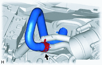
REMOVE HEATER WATER OUTLET HOSE A (for 2GR-FXE)
-
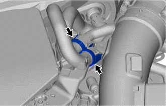
Remove the water hose set.
-
Using pliers, grip the claws of the clip and slide the clip.
-
Disconnect the heater water inlet hose A (engine side).
-
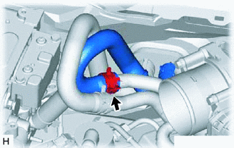
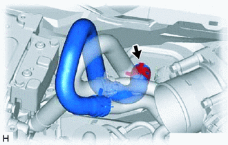
Using pliers, grip the claws of the clip and slide the clip.
-
Disconnect the heater water outlet hose A (engine side).
-
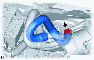
Using pliers, grip the claws of the clip and slide the clip.
-
Disconnect the heater water outlet hose A (unit side) and remove it.
-
-
REMOVE HEATER WATER INLET HOSE A (for 2GR-FXE)
-
Using pliers, grip the claws of the clip and slide the clip.
-
Disconnect the heater water inlet hose A (unit side) and remove it.
-
-
DISCONNECT HEATER WATER OUTLET HOSE A (for 2AR-FSE)
-
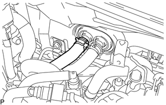
Using pliers, grip the claws of the clip and slide the clip.
-
Disconnect the heater water outlet hose A.
-
-
DISCONNECT HEATER WATER INLET HOSE A (for 2AR-FSE)
-
Using pliers, grip the claws of the clip and slide the clip.
-
Disconnect the heater water inlet hose A.
-
-
REMOVE FRONT SEAT ASSEMBLY
-
for Sports Seat Type:
-
for Luxury Seat Type:
-
for Standard Seat Type:
-
-
REMOVE REAR SEAT ASSEMBLY
-
REMOVE INSTRUMENT PANEL SAFETY PAD SUB-ASSEMBLY
-
REMOVE AIR DUCT PLUG
Tech Tips
Use the same procedure for both air duct plugs.
-
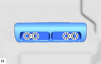
Detach the 4 claws and remove the air duct plug.
-
-
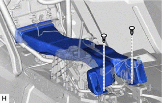
REMOVE REAR NO. 5 AIR DUCT
Tech Tips
Use the same procedure for both rear No. 5 air ducts.
-
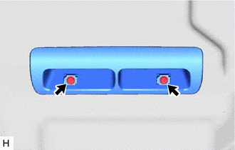
Remove the 2 screws and rear No. 5 air duct.
-
-
REMOVE FRONT FLOOR CARPET ASSEMBLY
Tech Tips
It is not necessary to fully remove the floor carpet. Partially remove it so that the instrument panel reinforcement assembly with air conditioning unit assembly can be removed in a later step.
-
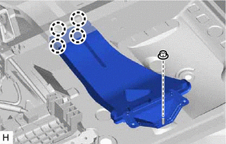
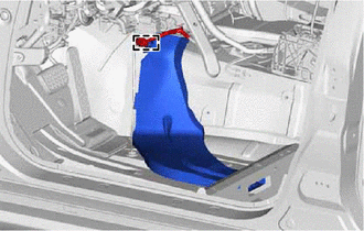
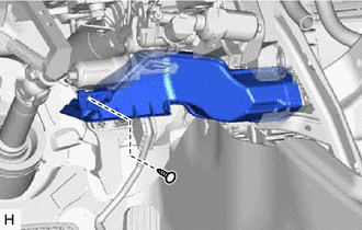
REMOVE REAR NO. 4 AIR DUCT
-
Remove the nut or clip.
Tech Tips
The rear No. 4 air duct is installed with a nut or clip.
-
Detach the 4 claws and remove the rear No. 4 air duct.
-
-
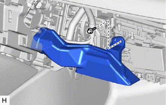
REMOVE REAR NO. 2 AIR DUCT
-
Remove the nut or clip.
Tech Tips
The rear No. 2 air duct is installed with a nut or clip.
-
Detach the 4 claws and remove the rear No. 2 air duct.
-
-
REMOVE REAR NO. 1 AIR DUCT
-
Detach the clamp.
-
Remove the rear No. 1 air duct.
-
-
REMOVE REAR NO. 3 AIR DUCT
-
Detach the clamp.
-
Remove the rear No. 3 air duct.
-
-
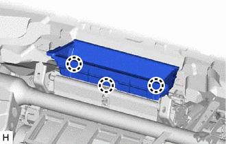
REMOVE NO. 1 CONSOLE BOX DUCT
-
Remove the 2 clips and No. 1 console box duct.
-
-
REMOVE NO. 1 AIR DUCT SUB-ASSEMBLY
-
Remove the clip and No. 1 air duct sub-assembly.
-
-
REMOVE NO. 2 AIR DUCT SUB-ASSEMBLY
-
Remove the screw and No. 2 air duct sub-assembly.
-
-
REMOVE STEERING COLUMN ASSEMBLY
-
REMOVE LOWER DEFROSTER NOZZLE ASSEMBLY
-
Detach the 3 claws and remove the lower defroster nozzle assembly.
-
-
REMOVE AIR HOSE
-
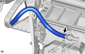
Remove the air hose.
-
-
REMOVE AIR CONDITIONING AMPLIFIER ASSEMBLY
-
REMOVE QUICK HEATER ASSEMBLY (w/ PTC Heater)
-
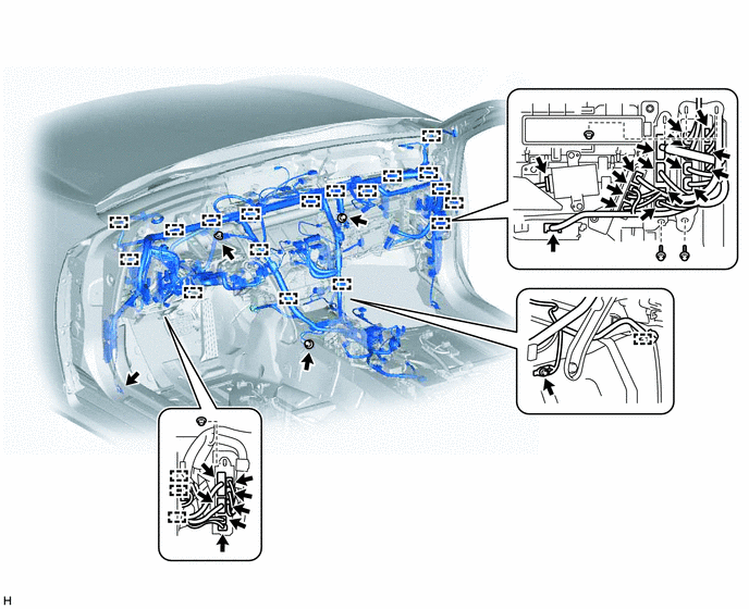
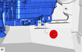
REMOVE INSTRUMENT PANEL REINFORCEMENT ASSEMBLY WITH AIR CONDITIONING UNIT ASSEMBLY
-
Remove the 2 grommets.
-
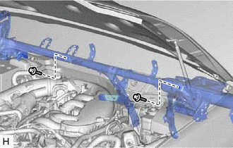
Remove the 2 bolts.
-
Detach the clamps and disconnect the connectors.
-
Remove the bolts and nuts.
-
Remove the nut.
-
Remove the 6 caps.
-
Remove the 9 bolts.
-
Using a 8 mm hexagon wrench, loosen the 3 collars.
-
Remove the instrument panel reinforcement assembly with air conditioning unit assembly.
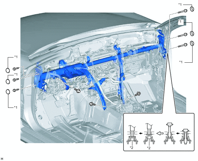
Text in Illustration *1 Cap *2 Collar
-
-
REMOVE AIR CONDITIONING UNIT
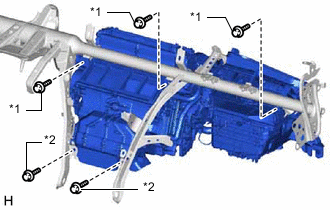
Text in Illustration *1 Bolt *2 Screw
-
Remove the 3 bolts, 2 screws and air conditioning unit.
-