SEAT BELT WARNING SYSTEM TERMINALS OF ECU
-
CHECK COMBINATION METER ASSEMBLY

-
Disconnect the N40 combination meter assembly connector.
-
Measure the resistance and voltage according to the value(s) in the table below.
Tester Connection Wiring Color Terminal Description Condition Specified Condition N40-21 (IG+) - Body ground W - Body ground Ignition power supply
(IG signal)
Power switch off Below 1 V Power switch on (IG) 11 to 14 V N40-22 (B) - Body ground P - Body ground Auxiliary battery power supply Always 11 to 14 V N40-31 (ES) - Body ground W-B - Body ground Ground Always Below 1 Ω -
Reconnect the N40 combination meter assembly connector.
-
Measure the voltage according to the value(s) in the table below.
Tester Connection Wiring Color Terminal Description Condition Specified Condition N40-6 (PBKL) - Body ground W - Body ground Front passenger side seat belt buckle switch signal Power switch on (IG), front passenger side seat belt fastened 11 to 14 V Power switch on (IG), front passenger side seat belt unfastened Below 1 V N40-7 (PODS) - Body ground B - Body ground Front passenger seat condition signal Power switch on (IG), sitting on front passenger seat 11 to 14 V Power switch on (IG), not sitting on front passenger seat Below 1 V
-
-
CHECK CENTER AIRBAG SENSOR ASSEMBLY
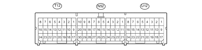
Terminal No. Terminal Symbol Destination U12-15*1 LBE+ Front seat inner belt assembly LH U12-23*1 LBE- Front seat inner belt assembly LH T12-10*2 RBE+ Front seat inner belt assembly RH T12-18*2 RBE- Front seat inner belt assembly RH
-
*1: for LHD
-
*2: for RHD
-