VEHICLE PROXIMITY NOTIFICATION SYSTEM "P" Position Switch Circuit
DESCRIPTION
When the vehicle approaching speaker controller detects that the shift lever is in P, vehicle approaching speaker operation is stopped. When the shift lever is in P, the main body ECU (driver side junction block) sends a signal to the vehicle approaching speaker controller.
WIRING DIAGRAM
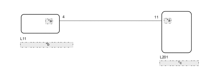
| *a | SFTP |
| *b | Main Body ECU (Driver Side Junction Block) |
| *c | Vehicle Approaching Speaker Controller |
CAUTION / NOTICE / HINT
Note
-
The vehicle proximity notification system uses a CAN communication system. Inspect the communication function by following How to Proceed with Troubleshooting.
-
Troubleshoot the vehicle proximity notification system after confirming that the communication system is functioning properly.
PROCEDURE
-
READ VALUE USING GTS (SHIFT P SIGNAL)
-
Connect the GTS to the DLC3.
-
Turn the power switch on (IG).
-
Turn the GTS on.
-
Enter the following menus: Body Electrical / Main Body / Data List.
-
Check the value(s) by referring to the table below.
Main Body Tester Display Measurement Item/Range Normal Condition Diagnostic Note Shift P Signal Shift P position signal/ON or OFF ON: Shift lever in P
OFF: Shift lever not in P
- OK The display is as specified in the normal condition column. Result Proceed to OK NG
NG 
GO TO ENTRY AND START SYSTEM Click here
OK 
-
-
CHECK HARNESS AND CONNECTOR (VEHICLE APPROACHING SPEAKER CONTROLLER - MAIN BODY ECU [DRIVER SIDE JUNCTION BLOCK])
-
Disconnect the L201 vehicle approaching speaker controller connector.
-
Disconnect the L11 main body ECU (driver side junction block) connector.
-
Measure the resistance according to the value (s) in the table below.
Standard Resistance Tester Connection Condition Specified Condition L201-11 (SFTP) - L11-4 (SFTP) Always Below 1 Ω L201-11 (SFTP) - Body ground Always 10 kΩ or higher Result Proceed to OK NG
OK
PROCEED TO NEXT SUSPECTED AREA SHOWN IN PROBLEM SYMPTOMS TABLE Click here
NG
REPAIR OR REPLACE HARNESS OR CONNECTOR
-