SLIDING ROOF SYSTEM Sliding Roof ECU Power Source Circuit
DESCRIPTION
If the sliding function and tilt function do not operate, there may be a malfunction in the sliding roof ECU power source circuit.
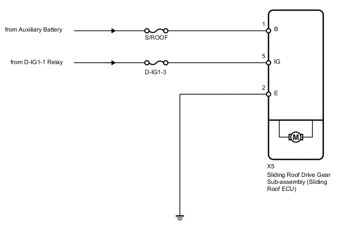
WIRING DIAGRAM
PROCEDURE
-
INSPECT FUSE (S/ROOF, D-IG1-5)
-
Remove the S/ROOF and D-IG1-5 fuses from the main body ECU (driver side junction block).
-
Measure the resistance according to the value(s) in the table below.
Standard resistance Tester Connection Condition Specified Condition S/ROOF fuse Always Below 1 Ω D-IG1-5 fuse Always Below 1 Ω
NG 
REPLACE FUSE
OK 
-
-
CHECK HARNESS AND CONNECTOR (SLIDING ROOF DRIVE GEAR - BODY GROUND)
-
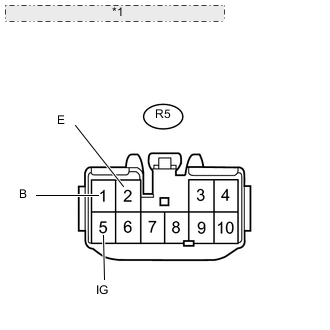
*1 Front view of wire harness connector: (to Sliding Roof Drive Gear) Disconnect the X5 drive gear connector.
-
Measure the resistance and voltage according to the value(s) in the table below.
Standard resistance Tester Connection Condition Specified Condition X5-2 (E) - Body ground Always Below 1 Ω Standard voltage Tester Connection Switch Condition Specified Condition X5-1 (B) - Body ground Always 11 to 14 V X5-5 (IG) - Body ground Power switch OFF Below 1 V X5-5 (IG) - Body ground Power switch ON (IG) 11 to 14 V
OK
REPLACE SLIDING ROOF DRIVE GEAR SUB-ASSEMBLY (SLIDING ROOF ECU) Click here
NG
REPAIR OR REPLACE HARNESS OR CONNECTOR
-