FRONT DOOR REMOVAL

CAUTION / NOTICE / HINT
Tech Tips
-
Use the same procedure for the RH and LH sides.
-
The procedure listed below is for the LH side.
PROCEDURE
-
PRECAUTION
Note
After turning the power switch off, waiting time may be required before disconnecting the cable from the auxiliary battery terminal. Therefore, make sure to read the disconnecting the cable from the auxiliary battery terminal notice before proceeding with work Click here.
-
REMOVE LUGGAGE COMPARTMENT MAT SUB-ASSEMBLY (w/ Spare Tire)
-
REMOVE DECK BOARD ASSEMBLY (w/o Spare Tire)
-
REMOVE DECK TRIM SIDE BOARD LH (w/o Spare Tire)
-
REMOVE BATTERY SERVICE HOLE COVER LH
-
DISCONNECT CABLE FROM NEGATIVE AUXILIARY BATTERY TERMINAL
CAUTION:
Wait at least 90 seconds after disconnecting the cable from the negative (-) auxiliary battery terminal to disable the SRS system.
Note
When disconnecting the cable, some systems need to be initialized after the cable is reconnected Click here.
-
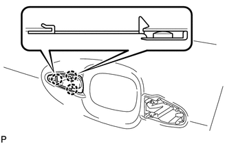
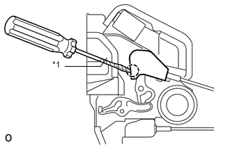
REMOVE FRONT DOOR INSIDE HANDLE BEZEL PLUG LH
-
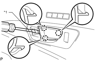
Text in Illustration *1 Protective Tape Using a screwdriver, detach the 3 claws and remove the front door inside handle bezel plug LH.
Tech Tips
Tape the screwdriver tip before use.
-
-
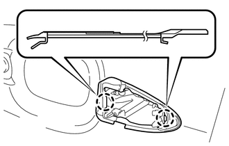
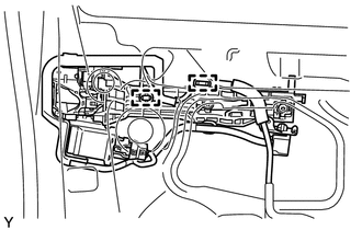
REMOVE POWER WINDOW REGULATOR MASTER SWITCH ASSEMBLY WITH FRONT DOOR ARMREST BASE PANEL
-
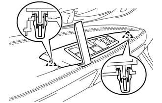
Using a moulding remover D, detach the 2 clips.
-
Disconnect the connector and remove the power window regulator master switch assembly with front door armrest base panel.
Tech Tips
Tape the screwdriver tip before use.
-
-
REMOVE FRONT DOOR TRIM BOARD SUB-ASSEMBLY LH
-
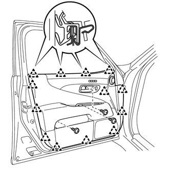
Remove the 3 screws.
-
Detach the 13 clips and remove the front door trim board sub-assembly LH.
-
Disconnect the connector.
-
Disconnect the 2 cables from the inside handle.
-
-
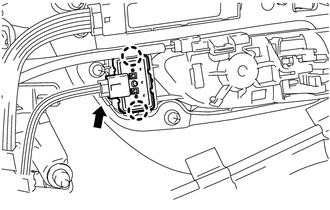
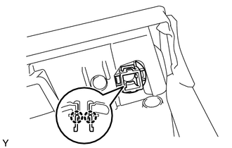
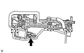
REMOVE FRONT DOOR INSIDE HANDLE ILLUMINATION LIGHT ASSEMBLY LH
-
Detach the claw, disconnect the connector and then remove the front door inside handle illumination light assembly LH.
-
-
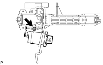
REMOVE COURTESY LIGHT ASSEMBLY
-
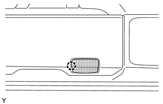
Detach the claw and remove the courtesy light assembly.
-
Disconnect the connector.
-
-
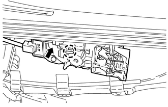
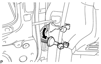
REMOVE HEIGHT ADJUSTABLE ANCHOR SWITCH
-
Disconnect the connector.
-
Detach the 2 claws and remove the height adjustable anchor switch.
-
-
REMOVE SEAT MEMORY SWITCH
-
REMOVE INDICATOR LIGHT ASSEMBLY
-
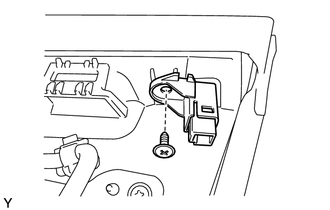
Disconnect the connector.
-
Remove the screw and indicator light assembly.
-
-
REMOVE INDICATOR LIGHT BRACKET
-
Detach the 2 claws and remove the indicator light bracket.
-
-
REMOVE INDICATOR LIGHT COVER
-
Remove the indicator light cover.
-
-
REMOVE FRONT DOOR TRIM COVER LH
-
Text in Illustration *1 Cushion Remove the cushion.
-
Using a clip remover, detach the 5 clips.
-
-
REMOVE FRONT DOOR BELT MOULDING END COVER REAR LH
-
Detach the claw and front door belt moulding end cover rear LH.
-
-
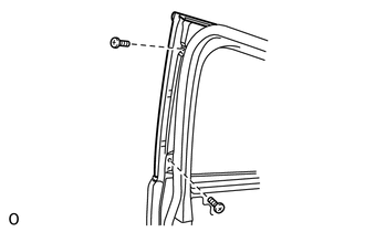
REMOVE DOOR FRAME GARNISH LH
-
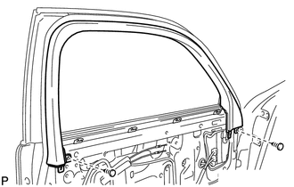
Remove the 2 clips and door frame garnish LH.
-
-
REMOVE FRONT NO. 1 SPEAKER ASSEMBLY
-
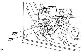
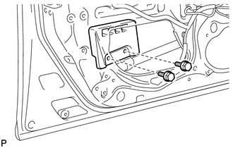
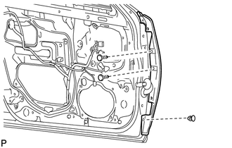
REMOVE FRONT MULTIPLEX NETWORK DOOR ECU LH
-
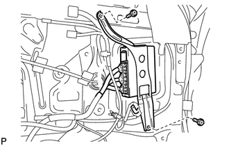
Remove the 2 screws and front multiplex network door ECU LH.
-
Disconnect the 3 connectors.
-
-
REMOVE FRONT DOOR NO. 2 SERVICE HOLE COVER LH
-
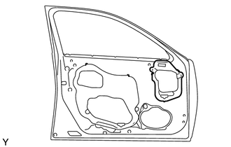
Remove the front door No. 2 service hole cover LH.
Tech Tips
Remove the remaining tape on the door.
-
-
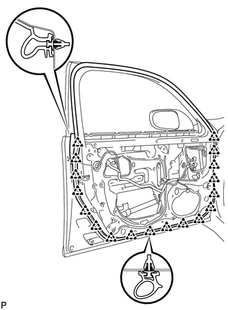
REMOVE FRONT DOOR SERVICE HOLE COVER LH
-
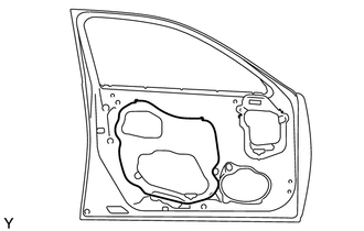
Remove the front door service hole cover LH.
Tech Tips
Remove the remaining tape on the door.
-
-
REMOVE OUTER REAR VIEW MIRROR ASSEMBLY LH
-
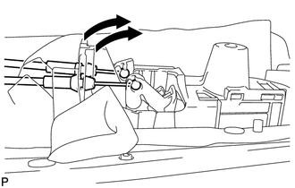
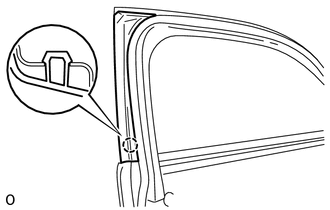
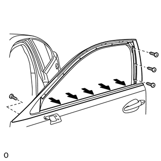
REMOVE FRONT DOOR GLASS INNER WEATHERSTRIP LH
-
Remove the front door glass inner weatherstrip LH by pulling it upward in the direction indicated by the arrow in the illustration.
-
-
REMOVE FRONT DOOR GLASS SUB-ASSEMBLY LH
-
Connect the front door ECU LH.
-
Temporarily install the power window regulator master switch assembly with front door armrest base panel.
-
Connect the cable to the negative (-) battery terminal.
-
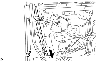
Remove the hole plug.
-
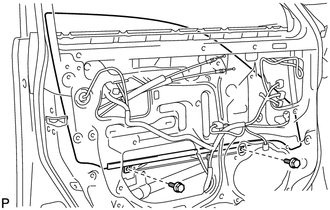
Move the front window regulator sub-assembly LH so that the front door glass sub-assembly LH bolts can be seen.
-
Disconnect the cable from the negative (-) battery terminal.
Note
When disconnecting the cable, some systems need to be initialized after the cable is reconnected Click here.
-
Remove the 2 bolts.
Note
Be careful when removing the bolts as the glass may fall and become damaged.
-
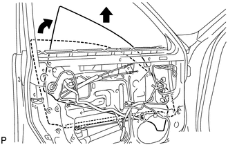
Remove the front door glass sub-assembly in the direction indicated by the arrows in the illustration.
Tech Tips
Remove the glass upward.
Note
Be careful not to damage the glass.
-
Remove the power window regulator master switch assembly with front door armrest base panel.
-
Disconnect the front door ECU LH.
-
-
REMOVE FRONT DOOR GLASS RUN LH
-
Remove the front door glass run LH.
-
-
REMOVE FRONT DOOR WEATHERSTRIP LH
-
REMOVE FRONT DOOR WINDOW FRONT FRAME MOULDING LH
-
REMOVE FRONT DOOR BELT MOULDING SUB-ASSEMBLY LH
-
Put a 4.5 mm (0.177 in.) drill bit into a drill.
-
Wind tape around the drill bit approximately 5 mm (0.197 in.) from the tip of the drill, as shown in the illustration.
-
Lightly press the drill against the rivet shown in the illustration, and drill off the rivet's flange.
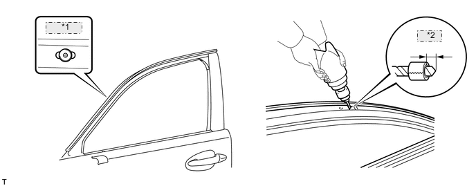
*1 Rivet (C) *2 5.0 mm CAUTION:
Be careful of the drilled rivet as it may become hot.
Note
-
Pressing the drill too firmly will cause the rivet to turn and result in the rivet not being drilled through.
-
Do not pry the rivet with the drill, because this may cause damage to the installation holes of the rivet or the drill bit.
-
-
Using a vacuum cleaner, remove the rivet fragments and shavings from the drilled area.
-
Remove the 2 screws.
-
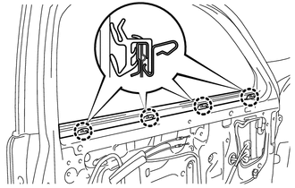
Loosen the 5 belt line screws indicated by the arrows in the illustration.
-
Remove the 4 screws and front door sub-assembly LH.
-
-
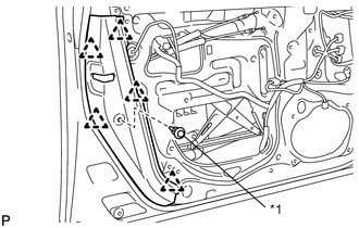
REMOVE FRONT DOOR WINDOW REGULATOR SUB-ASSEMBLY LH
-
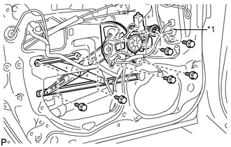
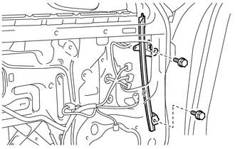
Text in Illustration *1 Temporary Bolt Disconnect the connector.
-
Loosen the temporary bolt.
Note
Do not remove the temporary bolt. If the temporary bolt is removed, the front door window regulator sub-assembly LH may fall and become damaged.
-
Remove the 5 bolts and front door window regulator sub-assembly LH.
Tech Tips
Remove the window regulator through the service hole.
Note
Be careful when removing the bolts as the window regulator may fall and become damaged.
-
Remove the temporary bolt from the front door window regulator sub-assembly LH.
-
-
REMOVE POWER WINDOW REGULATOR MOTOR ASSEMBLY LH
-
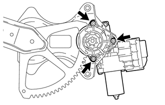
Using a T25 "TORX" driver, remove the 3 screws and power window regulator motor assembly LH.
Note
Be careful when removing the screws as the motor may fall and become damaged.
-
-
REMOVE FRONT DOOR FRONT LOWER FRAME SUB-ASSEMBLY LH
-
Remove the 2 bolts and front door front lower frame sub-assembly LH.
Tech Tips
Remove the frame through the service hole.
Note
Be careful when removing the bolts as the frame may fall and become damaged.
-
-
REMOVE FRONT DOOR REAR LOWER FRAME SUB-ASSEMBLY LH
-
Remove the 2 bolts and front door rear lower frame sub-assembly LH.
-
-
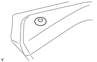
REMOVE FRONT DOOR OUTSIDE HANDLE COVER LH
-
Remove the hole plug.
-
Using a T30 "TORX" wrench, loosen the screw and remove the front door outside handle cover LH with the door lock key cylinder installed.
-
Remove the cylinder from the front door outside handle cover LH.
-
-
REMOVE FRONT DOOR OUTSIDE HANDLE ASSEMBLY LH
-
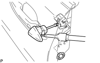
Using a T30 "TORX" wrench, loosen the screw.
-
Disconnect the connector.
-
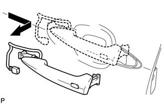
Remove the front door outside handle assembly LH by sliding and pulling it in the direction indicated by the arrow in the illustration.
Note
If the release plate is not pulled and held when removing the handle, the release plate will interfere with the handle and become damaged.
-
-
REMOVE FRONT DOOR OUTSIDE HANDLE PAD FRONT
-
Detach the 3 claws and remove the front door outside handle pad front.
-
-
REMOVE FRONT DOOR OUTSIDE HANDLE PAD REAR
-
Detach the 2 claws and remove the front door outside handle pad rear.
-
-
REMOVE NO. 2 SEPARATION DOOR STIFFENER CUSHION
-
Remove the 2 bolts and No. 2 separation door stiffener cushion.
-
-
REMOVE FRONT DOOR LOCK ASSEMBLY LH
-
REMOVE FRONT DOOR LOCK REMOTE CONTROL CABLE ASSEMBLY LH
-
Text in Illustration *1 Protective Tape Using a screwdriver, detach the claw.
Tech Tips
Tape the screwdriver tip before use.
-
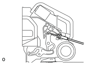
Remove the front door lock remote control cable assembly LH.
-
-
REMOVE FRONT DOOR INSIDE LOCKING CABLE ASSEMBLY LH
-
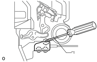
Text in Illustration *1 Protective Tape Using a screwdriver, detach the 3 claws.
Tech Tips
Tape the screwdriver tip before use.
-
Remove the front door inside locking cable assembly LH.
-
-
REMOVE FRONT DOOR OUTSIDE HANDLE FRAME SUB-ASSEMBLY LH
-
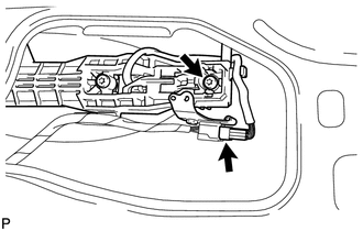
Using a T30 "TORX" wrench, remove the screw and detach the 2 wire harness clamps.
Tech Tips
Remove the outside handle frame through the service hole.
-
Disconnect the connector and detach the 3 clamps.
-
Remove the lock open rod from the front door outside handle frame sub-assembly LH.
-
-
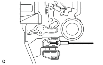
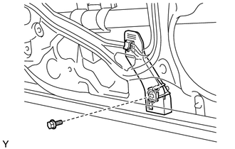
REMOVE DOOR ELECTRICAL KEY OSCILLATOR (for Front Door)
-
Remove the screw and door electrical key oscillator.
-
-
REMOVE FRONT DOOR NO. 2 STIFFENER CUSHION
-
Remove the bolt and the front door No. 2 stiffener cushion.
-
-
REMOVE FRONT DOOR LOWER FRAME GARNISH PAD LH
-
Remove the 2 bolts and front door lower frame garnish pad LH.
-
-
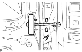
REMOVE DOOR CHECK COVER LH
-
Remove the door check cover LH.
-
-
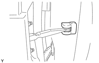
REMOVE FRONT DOOR CHECK ASSEMBLY LH
-
Remove the bolt and 2 nuts and front door check assembly LH.
Tech Tips
Remove the door check through the service hole.
Note
Be careful when removing the bolts as the door check may fall and become damaged.
-
-
REMOVE FRONT DOOR WEATHERSTRIP LH
-
Using a clip remover, detach the clips and remove the front door weatherstrip LH.
Tech Tips
If clips are damaged during removal, replace them.
-
-
REMOVE FRONT DOOR WIRE LH
-
Disconnect the connector.
-
-
REMOVE FRONT DOOR PANEL SUB-ASSEMBLY LH
-
Remove the 2 bolts and front door panel sib-assembly LH.
CAUTION:
Be sure to perform this procedure with 2 or more persons as the part is very heavy.
-
-
REMOVE FRONT DOOR NO. 3 WEATHERSTRIP LH
-
Remove the 3 clips and front door No. 3 weatherstrip LH.
-