SEAT VIBRATION SYSTEM Seat Vibrator does not Operate
DESCRIPTION
The position control ECU operates the seat vibrator based on the signals from the seat vibrator switch.
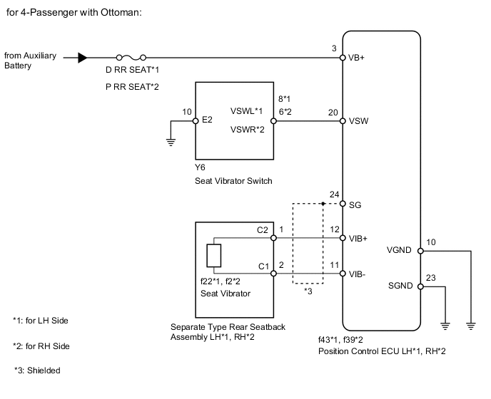
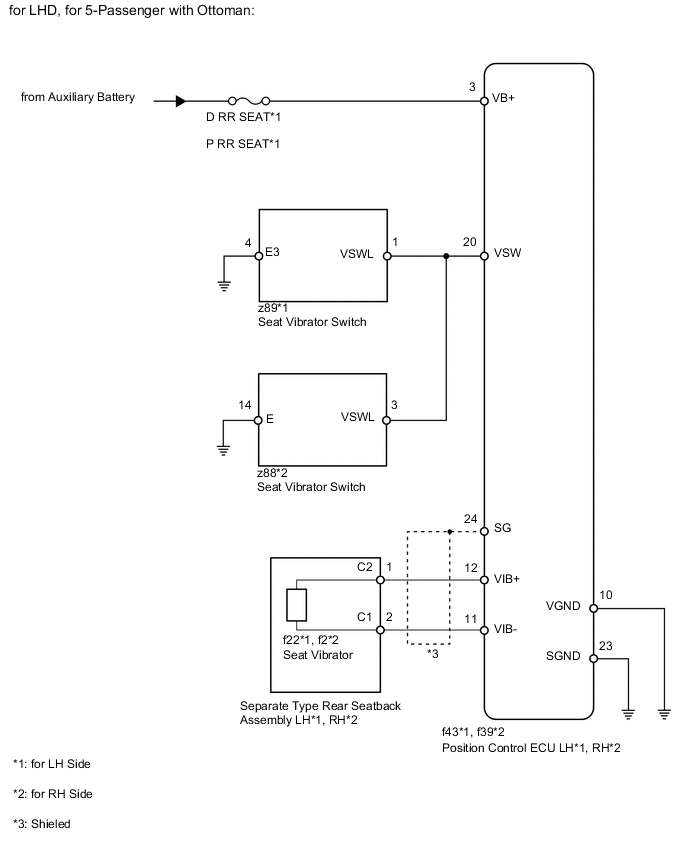
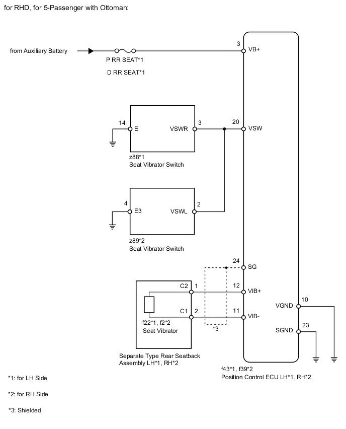
WIRING DIAGRAM
PROCEDURE
-
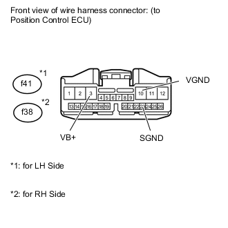
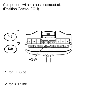
CHECK HARNESS AND CONNECTOR (POSITION CONTROL ECU - BATTERY AND BODY GROUND)
-
for LH Side:
Disconnect the f43 ECU connector.
-
for RH Side:
Disconnect the f39 ECU connector.
-
Measure the voltage according to the value(s) in the table below.
Standard voltage for LH Side Tester Connection Condition Specified Condition f43-3 (VB+) - Body ground Always 11 to 14 V for RH Side Tester Connection Condition Specified Condition f39-3 (VB+) - Body ground Always 11 to 14 V -
Measure the resistance according to the value(s) in the table below.
Standard resistance for LH Side Tester Connection Condition Specified Condition f43-10 (VGND) - Body ground Always Below 1 Ω f43-23 (SGND) - Body ground Always Below 1 Ω for RH Side Tester Connection Condition Specified Condition f39-10 (VGND) - Body ground Always Below 1 Ω f39-23 (SGND) - Body ground Always Below 1 Ω
NG 
REPAIR OR REPLACE HARNESS OR CONNECTOR
OK 
-
-
CHECK POSITION CONTROL ECU (SWITCH CIRCUIT)
-
Remove the position control ECU with its connectors still connected.
-
Measure the voltage according to the value(s) in the table below.
Standard voltage for LH Side Tester Connection Switch Condition Specified Condition f43-20 (VSW) - Body ground Power switch on (IG)
Vibrator switch OFF
Below 1 V Power switch on (IG)
Vibrator switch ON
2 to 3 V Other than above 4 to 5 V for RH Side Tester Connection Switch Condition Specified Condition f39-20 (VSW) - Body ground Power switch on (IG)
Vibrator switch OFF
Below 1 V Power switch on (IG)
Vibrator switch ON
2 to 3 V Other than above 4 to 5 V
NG 
CHECK SEAT TYPE Click here
OK
-
-
CHECK POSITION CONTROL ECU
-
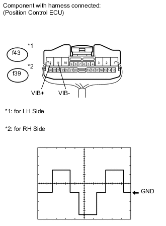
Remove the position control ECU with its connectors still connected.
-
Using an oscilloscope, check the waveform.
Measurement condition (for LH Side) Item Content Terminal No. (Symbols) f43-12 (VIB+) - f43-11 (VIB-) Tool Setting 5 V/DIV., 20 ms/DIV. Condition power switch on (IG)
Vibrator switch ON
Measurement condition (for RH Side) Item Content Terminal No. (Symbols) f39-12 (VIB+) - f39-11 (VIB-) Tool Setting 5 V/DIV., 20 ms/DIV. Condition Power switch on (IG)
Vibrator switch ON
OK Waveform is as shown in the illustration.
OK
REPLACE POSITION CONTROL ECU Click here
NG
CHECK HARNESS AND CONNECTOR (POSITION CONTROL ECU - SEAT VIBRATOR) Click here
-
-
CHECK SEAT TYPE
-
Check seat type.
Result Result Proceed to for 4-Passenger with Ottoman A for 5-Passenger with Ottoman B
B
CHECK HARNESS AND CONNECTOR (POSITION CONTROL ECU - SEAT VIBRATOR SWITCH AND BODY GROUND) Click here
A
-
-
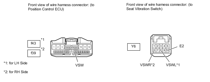
CHECK HARNESS AND CONNECTOR (POSITION CONTROL ECU - SEAT VIBRATOR SWITCH AND BODY GROUND)
-
Disconnect the Y6 switch connector.
-
for LH Side:
Disconnect the f43 ECU connector.
-
for RH Side:
Disconnect the f39 ECU connector.
-
Measure the resistance according to the values in the table below.
Standard resistance for LH Side Tester Connection Condition Specified Condition f43-20 (VSW) - Y6-8 (VSWL) Always Below 1 Ω Y6-10 (E2) - Body ground Always Below 1 Ω f43-20 (VSW) - Body ground Always 10 kΩ or higher for RH Side Tester Connection Condition Specified Condition f39-20 (VSW) - Y6-6 (VSWR) Always Below 1 Ω Y6-10 (E2) - Body ground Always Below 1 Ω f39-20 (VSW) - Body ground Always 10 kΩ or higher
NG
REPAIR OR REPLACE HARNESS OR CONNECTOR
OK
-
-
CHECK SEAT VIBRATOR SWITCH (OPERATION)
-
Replace the seat vibrator switch with a new or normally operating one. Perform an operation inspection.
OK Seat vibrator operates normally.
OK
END (SEAT VIBRATOR SWITCH IS DEFECTIVE)
NG
REPLACE POSITION CONTROL ECU Click here
-
-
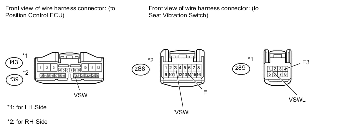
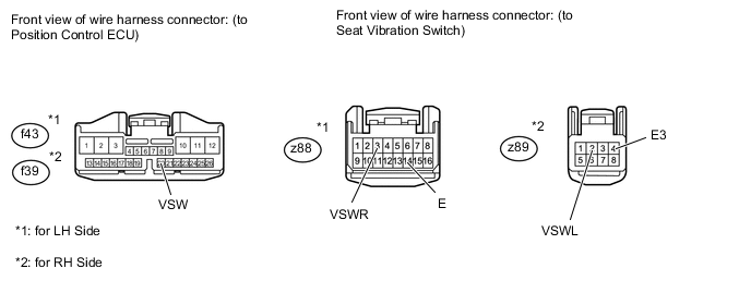
CHECK HARNESS AND CONNECTOR (POSITION CONTROL ECU - SEAT VIBRATOR SWITCH AND BODY GROUND)
Tech Tips
*1: LH Side
*2: RH Side
-
for LHD:
-
Disconnect the f43*1 or f39*2 ECU connector.
-
Disconnect the z88*1 or z89*2 switch connector.
-
-
for RHD:
-
Disconnect the f43*1 or f39*2 ECU connector.
-
Disconnect the z89*1 or z88*2 switch connector.
-
-
Measure the resistance according to the values in the table below.
Standard resistance for LHD Tester Connection Condition Specified Condition f43-20 (VSW) - z89-1 (VSWL)*1 Always Below 1 Ω z89-4 (E3) - Body ground*1 Always Below 1 Ω f43-20 (VSW) - Body ground*1 Always 10 kΩ or higher f39-20 (VSW) - z88-3 (VSWL)*2 Always Below 1 Ω z88-14 (E) - Body ground*2 Always Below 1 Ω f39-20 (VSW) - Body ground*2 Always 10 kΩ or higher for RHD Tester Connection Condition Specified Condition f43-20 (VSW) - z88-3 (VSWR)*1 Always Below 1 Ω z88-14 (E) - Body ground*1 Always Below 1 Ω f43-20 (VSW) - Body ground*1 Always 10 kΩ or higher f39-20 (VSW) - z89-2 (VSWL)*2 Always Below 1 Ω z89-4 (E3) - Body ground*2 Always Below 1 Ω f39-20 (VSW) - Body ground*2 Always 10 kΩ or higher
NG
REPAIR OR REPLACE HARNESS OR CONNECTOR
OK
-
-
CHECK SEAT VIBRATOR SWITCH (OPERATION)
-
Replace the seat vibrator switch with a new or normally operating one. Perform an operation inspection.
OK Seat vibrator operates normally.
OK
END (SEAT VIBRATOR SWITCH IS DEFECTIVE)
NG
REPLACE POSITION CONTROL ECU Click here
-
-
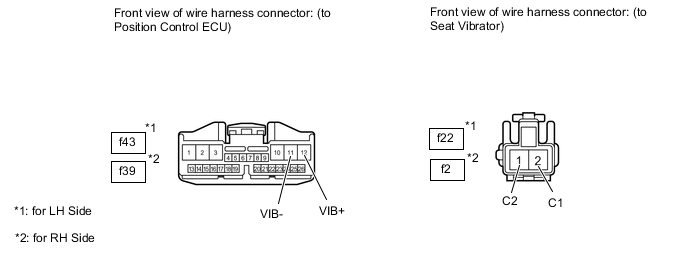
CHECK HARNESS AND CONNECTOR (POSITION CONTROL ECU - SEAT VIBRATOR)
-
for LH Side:
-
Disconnect the f43 ECU connector.
-
Disconnect the f22 vibrator connector.
-
-
for RH Side:
-
Disconnect the f39 ECU connector.
-
Disconnect the f2 vibrator connector.
-
-
Measure the resistance according to the value(s) in the table below.
Standard resistance for LH Side Tester Connection Condition Specified Condition f43-12 (VIB+) - f22-1 (C2) Always Below 1 Ω f43-11 (VIB-) - f22-2 (C1) Always Below 1 Ω f43-12 (VIB+) - Body ground Always 10 kΩ or higher f43-11 (VIB-) - Body ground Always 10 kΩ or higher for RH Side Tester Connection Condition Specified Condition f39-12 (VIB+) - f2-1 (C2) Always Below 1 Ω f39-11 (VIB-) - f2-2 (C1) Always Below 1 Ω f39-12 (VIB+) - Body ground Always 10 kΩ or higher f39-11 (VIB-) - Body ground Always 10 kΩ or higher
NG
REPAIR OR REPLACE HARNESS OR CONNECTOR
OK
-
-
CHECK POSITION CONTROL ECU (OPERATION)
-
Replace the position control ECU with a new or normally operating one. Perform an operation inspection.
OK Seat vibrator operates normally. Result Result Proceed to OK A NG (w/o Ottoman) B NG (w/ Ottoman) C
A
END (POSITION CONTROL ECU IS DEFECTIVE)
B
REPLACE SEPARATE TYPE REAR SEATBACK ASSEMBLY (SEAT VIBRATOR) Click here
C
REPLACE SEPARATE TYPE REAR SEATBACK ASSEMBLY (SEAT VIBRATOR) Click here
-