SEAT VIBRATION SYSTEM TERMINALS OF ECU
-
CHECK SEAT VIBRATION MODULE ASSEMBLY
-
Disconnect the S29 connector.

-
Measure the voltage and resistance of the wire harness side connector.
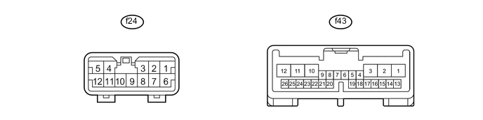
Terminal No. (Symbols) Wiring Color Terminal Description Condition Specified Condition S29-1 (IG) - S29-8 (GND) BR - W-B Ignition power supply Power switch off Below 1 V Power switch on (IG) 11 to 14 V S29-8 (GND) - Body ground W-B - Body ground Ground Always Below 1 Ω If the result is not as specified, there may be a malfunction on the wire harness side.
-
-
CHECK POSITION CONTROL ECU LH
-
Disconnect the f43 ECU connector.
-
Measure the voltage and resistance of the wire harness connectors.
Terminal No. (Symbols) Wiring Color Terminal Description Condition Specified Condition f43-3 (VB+) - f43-10 (VGND) W - W-B Power source Always 11 to 14 V f43-10 (VGND) - Body ground W-B - Body ground Ground Always Below 1 Ω f43-23 (SGND) - Body ground BR - Body ground Ground Always Below 1 Ω If the result is not as specified, there may be a malfunction on the wire harness side.
-
Reconnect the f43 ECU connector.
-
Measure the voltage and resistance of the connectors.
Terminal No. (Symbols) Wiring Color Terminal Description Condition Specified Condition f43-1 (LVM+) - f43-10 (VGND) LG - W-B Lumbar motor signal (forward) Power switch on (IG)
Lumbar switch (forward) ON
11 to 14 V Other than above Below 1 V f43-2 (LVM-) - f43-10 (VGND) W - W-B Lumbar motor signal (rearward) Power switch on (IG)
Lumbar switch (rearward) ON
11 to 14 V Other than above Below 1 V f43-12 (VIB+) - f43-11 (VIB-) L - P Vibrator signal Power switch on (IG)
Vibrator switch ON
Pulse generation
(See waveform 1)
Other than above Below 1 V f43-20 (VSW) - f43-23 (SGND) GR - BR Vibrator switch signal Power switch on (IG)
Vibrator switch OFF pushed
Below 1 V Power switch on (IG)
Vibrator switch ON pushed
2 to 3 V Other than above 4 to 5 V f43-21 (MSW) - f43-23 (SGND) L - BR Lumbar switch signal Power switch on (IG)
Lumbar switch (rearward) ON
Below 1 V Power switch on (IG)
Lumbar switch (forward) ON
2 to 3 V Other than above 4 to 5 V f43-10 (VGND) - Body ground W-B - Body ground Ground Always Below 1 Ω -
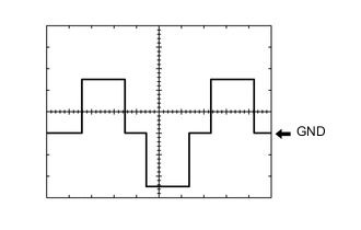
Using an oscilloscope, check waveform 1.
Item Content Terminal No. (Symbols) f43-12 (VIB+) - f43-11 (VIB-) Tool Setting 5 V/DIV., 20 ms/DIV. Condition Power switch on (IG)
Vibrator switch ON
-
-
CHECK POSITION CONTROL ECU RH
-
Disconnect the f39 ECU connector.

-
Measure the voltage and resistance of the wire harness connectors.
Terminal No. (Symbols) Wiring Color Terminal Description Condition Specified Condition f39-3 (VB+) - f39-10 (VGND) W - W-B Power source Always 11 to 14 V f39-10 (VGND) - Body ground W-B - Body ground Ground Always Below 1 Ω f39-23 (SGND) - Body ground BR - Body ground Ground Always Below 1 Ω If the result is not as specified, there may be a malfunction on the wire harness side.
-
Reconnect the f39 ECU connector.
-
Measure the voltage and resistance of the connectors.
Terminal No. (Symbols) Wiring Color Terminal Description Condition Specified Condition f39-1 (LVM+) - f39-10 (VGND) LG - W-B Lumbar motor signal (forward) Power switch on (IG)
Lumbar switch (forward) ON
11 to 14 V Other than above Below 1 V f39-2 (LVM-) - f39-10 (VGND) W - W-B Lumbar motor signal (rearward) Power switch on (IG)
Lumbar switch (rearward) ON
11 to 14 V Other than above Below 1 V f39-12 (VIB+) - f39-11 (VIB-) L - P Vibrator signal Power switch on (IG)
Vibrator switch ON
Pulse generation
(See waveform 1)
Other than above Below 1 V f39-20 (VSW) - f39-23 (SGND) L - BR Vibrator switch signal Power switch on (IG)
Vibrator switch OFF pushed
Below 1 V Power switch on (IG)
Vibrator switch ON pushed
2 to 3 V Other than above 4 to 5 V f39-21 (MSW) - f39-23 (SGND) P - BR Lumbar switch signal Power switch on (IG)
Lumbar switch (rearward) ON
Below 1 V Power switch on (IG)
Lumbar switch (forward) ON
2 to 3 V Other than above 4 to 5 V f39-10 (VGND) - Body ground W-B - Body ground Ground Always Below 1 Ω -
Using an oscilloscope, check waveform 1.
Item Content Terminal No. (Symbols) f39-12 (VIB+) - f39-11 (VIB-) Tool Setting 5 V/DIV., 20 ms/DIV. Condition Power switch on (IG)
Vibrator switch ON
-