SEAT VIBRATION SYSTEM Position of Seat Vibrator cannot be Adjusted
DESCRIPTION
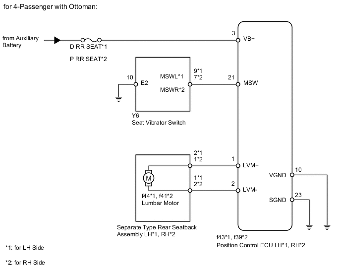
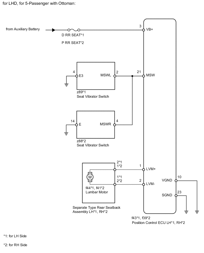
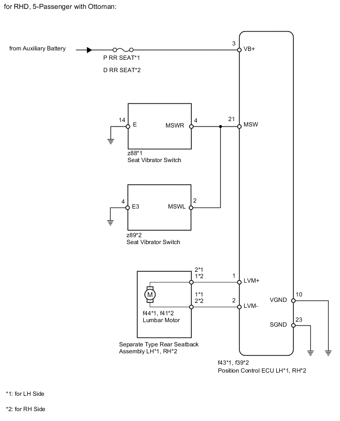
The position control ECU operates the lumbar motor based on the signals received from the seat vibrator switch to adjust the seat vibrator position.
WIRING DIAGRAM
PROCEDURE
-
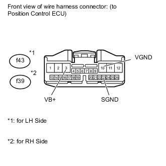
CHECK HARNESS AND CONNECTOR (POSITION CONTROL ECU - BATTERY AND BODY GROUND)
-
for LH Side:
Disconnect the f43 ECU connector.
-
for RH Side:
Disconnect the f39 ECU connector.
-
Measure the voltage according to the value(s) in the table below.
Standard voltage for LH Side Tester Connection Condition Specified Condition f43-3 (VB+) - Body ground Always 11 to 14 V for RH Side Tester Connection Condition Specified Condition f39-3 (VB+) - Body ground Always 11 to 14 V -
Measure the resistance according to the value(s) in the table below.
Standard resistance for LH Side Tester Connection Condition Specified Condition f43-10 (VGND) - Body ground Always Below 1 Ω f43-23 (SGND) - Body ground Always Below 1 Ω for RH Side Tester Connection Condition Specified Condition f39-10 (VGND) - Body ground Always Below 1 Ω f39-23 (SGND) - Body ground Always Below 1 Ω
NG 
REPAIR OR REPLACE HARNESS OR CONNECTOR
OK 
-
-
CHECK POSITION CONTROL ECU (SWITCH CIRCUIT)
-
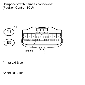
Remove the position control ECU with its connectors still connected
-
Measure the voltage according to the value(s) in the table below.
Standard voltage for LH Side Tester Connection Switch Condition Specified Condition f43-21 (MSW) - Body ground Power switch on (IG)
Lumbar switch (rearward) ON
Below 1 V Power switch on (IG)
Lumbar switch (forward) ON
2 to 3 V Other than above 4 to 5 V for RH Side Tester Connection Switch Condition Specified Condition f39-21 (MSW) - Body ground Power switch on (IG)
Lumbar switch (rearward) ON
Below 1 V Power switch on (IG)
Lumbar switch (forward) ON
2 to 3 V Other than above 4 to 5 V
NG 
CHECK SEAT TYPE Click here
OK
-
-
INSPECT SEPARATE TYPE REAR SEATBACK ASSEMBLY (LUMBAR MOTOR)
-
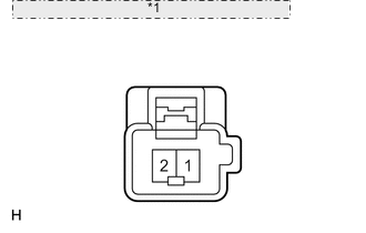
*1 Component without harness connected: (Lumbar Motor) Check the operation of the lumbar motor.
-
Apply battery voltage to the lumbar motor.
-
Check that the lumbar support adjuster moves smoothly.
OK for LH Side Measurement Condition Operation Direction Battery positive (+) → 2
Battery negative (-) → 1
Forward Battery positive (+) → 1
Battery negative (-) → 2
Backward for RH Side Measurement Condition Operation Direction Battery positive (+) → 1
Battery negative (-) → 2
Forward Battery positive (+) → 2
Battery negative (-) → 1
Backward Result Result Proceed to OK A NG (w/o Ottoman) B NG (w/ Ottoman) C
-
B
REPLACE SEPARATE TYPE REAR SEATBACK ASSEMBLY Click here
C
REPLACE SEPARATE TYPE REAR SEATBACK ASSEMBLY Click here
A
-
-
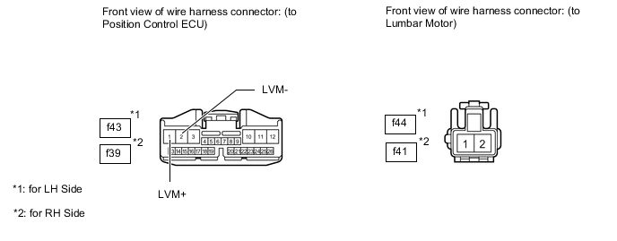
CHECK HARNESS AND CONNECTOR (POSITION CONTROL ECU - LUMBAR MOTOR)
-
for LH Side:
-
Disconnect the f43 ECU connector.
-
Disconnect the f44 motor connector.
-
-
for RH Side:
-
Disconnect the f39 ECU connector.
-
Disconnect the f41 motor connector.
-
-
Measure the resistance according to the value(s) in the table below.
Standard resistance for LH Side Tester Connection Condition Specified Condition f43-1 (LVM+) - f44-2 Always Below 1 Ω f43-2 (LVM-) - f44-1 Always Below 1 Ω f43-1 (LVM+) - Body ground Always 10 kΩ or higher f43-2 (LVM-) - Body ground Always 10 kΩ or higher for RH Side Tester Connection Condition Specified Condition f39-1 (LVM+) - f41-1 Always Below 1 Ω f39-2 (LVM-) - f41-2 Always Below 1 Ω f39-1 (LVM+) - Body ground Always 10 kΩ or higher f39-2 (LVM-) - Body ground Always 10 kΩ or higher Result Result Proceed to OK (w/ Ottoman) A OK (w/o Ottoman) B NG C
B
REPLACE POSITION CONTROL ECU Click here
C
REPAIR OR REPLACE HARNESS OR CONNECTOR
A
-
-
CHECK SEAT TYPE
-
Check seat type.
Result Result Proceed to for 4-Passenger with Ottoman A for 5-Passenger with Ottoman B
B
CHECK HARNESS AND CONNECTOR (POSITION CONTROL ECU - SEAT VIBRATOR SWITCH AND BODY GROUND) Click here
A
-
-
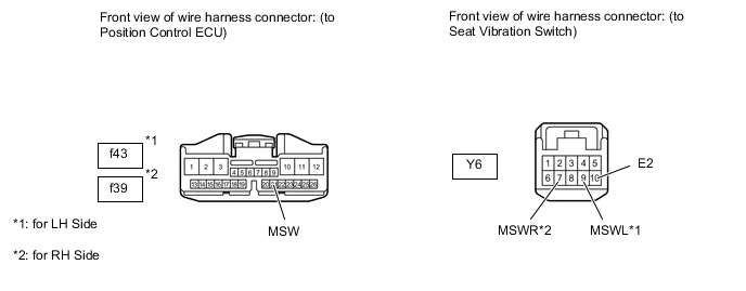
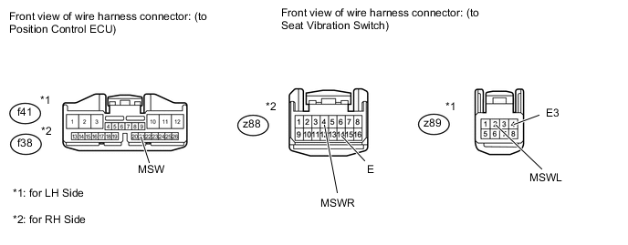
CHECK HARNESS AND CONNECTOR (POSITION CONTROL ECU - SEAT VIBRATOR SWITCH AND BODY GROUND)
-
for LH Side:
Disconnect the f43 ECU connector.
-
Disconnect the Y6 switch connector.
-
for RH Side:
Disconnect the f39 ECU connector.
-
Disconnect the Y6 switch connector.
-
Measure the resistance according to the value(s) in the table below.
Standard resistance for LH Side Tester Connection Condition Specified Condition f43-21 (MSW) - Y6-9 (MSWL) Always Below 1 Ω Y6-10 (E2) - Body ground Always Below 1 Ω f43-21 (MSW) - Body ground Always 10 kΩ or higher for RH Side Tester Connection Condition Specified Condition f39-21 (MSW) - Y6-7 (MSWR) Always Below 1 Ω Y6-10 (E2) - Body ground Always Below 1 Ω f39-21 (MSW) - Body ground Always 10 kΩ or higher
NG
REPAIR OR REPLACE HARNESS OR CONNECTOR
OK
-
-
CHECK SEAT VIBRATOR SWITCH (OPERATION)
-
Replace the seat vibrator switch with a new or normally operating one. Perform an operation inspection.
OK Lumbar motor operates normally.
OK
END (SEAT VIBRATOR SWITCH IS DEFECTIVE)
NG
REPLACE POSITION CONTROL ECU Click here
-
-
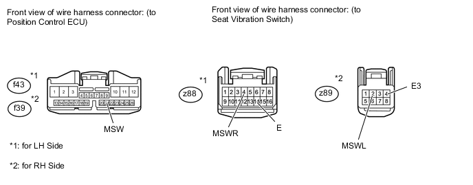
CHECK HARNESS AND CONNECTOR (POSITION CONTROL ECU - SEAT VIBRATOR SWITCH AND BODY GROUND)
Tech Tips
*1: LH Side
*2: RH Side
-
for LHD:
-
Disconnect the f43*1 or f39*2 ECU connector.
-
Disconnect the z88*1 or z89*2 switch connector.
-
-
for RHD:
-
Disconnect the f43*1 or f39*2 ECU connector.
-
Disconnect the z89*1 or z88*2 switch connector.
-
-
Measure the resistance according to the value(s) in the table below.
Standard resistance for LHD Tester Connection Condition Specified Condition f43-21 (MSW) - z89-2 (MSWLR)*1 Always Below 1 Ω z89-4 (E3) - Body ground*1 Always Below 1 Ω f43-21 (MSW) - Body ground*1 Always 10 kΩ or higher f39-21 (MSW) - z88-4 (MSWR)*2 Always Below 1 Ω z88-14 (E) - Body ground*2 Always Below 1 Ω f39-21 (MSW) - Body ground*2 Always 10 kΩ or higher for RHD Tester Connection Condition Specified Condition f43-21 (MSW) - z88-4 (MSWR)*1 Always Below 1 Ω z88-14 (E) - Body ground*1 Always Below 1 Ω f43-21 (MSW) - Body ground*1 Always 10 kΩ or higher f39-21 (MSW) - z89-2 (MSWL)*2 Always Below 1 Ω z89-4 (E3) - Body ground*2 Always Below 1 Ω f39-21 (MSW) - Body ground*2 Always 10 kΩ or higher
NG
REPAIR OR REPLACE HARNESS OR CONNECTOR
OK
-
-
CHECK SEAT VIBRATOR SWITCH (OPERATION)
-
Replace the seat vibrator switch with a new or normally operating one. Perform an operation inspection.
OK Lumbar motor operates normally.
OK
END (SEAT VIBRATOR SWITCH IS DEFECTIVE)
NG
REPLACE POSITION CONTROL ECU Click here
-