FRONT POWER SEAT CONTROL SYSTEM TERMINALS OF ECU
-
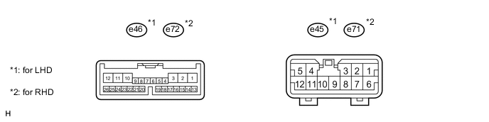
CHECK FRONT POWER SEAT SWITCH LH
-
for LHD:
Disconnect the e45 and e46 switch connectors.
-
for RHD:
Disconnect the e71 and e72 switch connectors.
-
Measure the voltage and resistance according to the value(s) in the table below.
for LHD Terminal No.
(Symbols)
Wiring Color Terminal Description Condition Specified Condition e45-6 (GND) - Body ground W-B - Body ground Ground Always Below 1 Ω e45-7 (+B) - e45-6 (GND) B-R - W-B Power source Always 11 to 14 V e46-4 (SYSB) - e45-6 (GND) B - W-B Power source Always 11 to 14 V for RHD Terminal No.
(Symbols)
Wiring Color Terminal Description Condition Specified Condition e71-6 (GND) - Body ground W-B - Body ground Ground Always Below 1 Ω e71-7 (+B) - e71-6 (GND) B - W-B Power source Always 11 to 14 V e72-4 (SYSB) - e71-6 (GND) R - W-B Power source Always 11 to 14 V -
for LHD:
Reconnect the e45 and e46 switch connectors.
-
for RHD:
Reconnect the e71 and e72 switch connectors.
-
Measure the voltage according to the value(s) in the table below.
for LHD Terminal No.
(Symbols)
Wiring Color Terminal Description Condition Specified Condition e46-12 (SLD+) - e45-6 (GND) B - W-B Sliding motor signal
(forward)
Seat moving forward using sliding switch 11 to 14 V Other Below 1 V e46-11 (SLD-) - e45-6 (GND) W - W-B Sliding motor signal
(rearward)
Seat moving rearward using sliding switch 11 to 14 V Other Below 1 V e46-10 (C+) - e45-6 (GND) W - W-B Seat cushion motor signal
(forward)
Seat cushion moving forward using cushion switch 11 to 14 V Other Below 1 V e45-4 (C-) - e45-6 (GND) R-B - W-B Seat cushion motor signal
(rearward)
Seat cushion moving rearward using cushion switch 11 to 14 V Other Below 1 V e46-1 (FRV+) - e45-6 (GND) R - W-B Front vertical motor signal
(upward)
Seat cushion front portion rising using front vertical switch 11 to 14 V Other Below 1 V e45-12 (FRV-) - e45-6 (GND) W - W-B Front vertical motor signal
(downward)
Seat cushion front portion lowering using front vertical switch 11 to 14 V Other Below 1 V e46-3 (RCL+) - e45-6 (GND) L - W-B Reclining motor signal
(forward)
Seatback moving forward using reclining switch 11 to 14 V Other Below 1 V e45-3 (RCL-) - e45-6 (GND) B-W - W-B Reclining motor signal
(rearward)
Seatback moving rearward using reclining switch 11 to 14 V Other Below 1 V e45-11 (H+) - e45-6 (GND) G-B - W-B Headrest motor signal
(upward)
Headrest moving upward using headrest switch 11 to 14 V Other Below 1 V e45-8 (H-) - e45-6 (GND) L - W-B Headrest motor signal
(downward)
Headrest moving downward using headrest switch 11 to 14 V Other Below 1 V e46-2 (RRV+) - e45-6 (GND) B-R - W-B Lifter motor signal
(upward)
Seat rising using lifter switch 11 to 14 V Other Below 1 V e45-5 (RRV-) - e45-6 (GND) Y - W-B Lifter motor signal
(downward)
Seat lowering using lifter switch 11 to 14 V Other Below 1 V e45-9 (LV+) - e45-6 (GND) R - W-B Lumbar motor signal
(upward)
Lumbar switch (upward) ON 11 to 14 V Other Below 1 V e45-2 (LV-) - e45-6 (GND) L-R - W-B Lumbar motor signal
(downward)
Lumbar switch (downward) ON 11 to 14 V Other Below 1 V e45-10 (L+) - e45-6 (GND) R-L - W-B Lumbar motor signal
(forward)
Lumbar switch (forward) ON 11 to 14 V Other Below 1 V e45-1 (L-) - e45-6 (GND) G-Y - W-B Lumbar motor signal
(rearward)
Lumbar switch (rearward) ON 11 to 14 V Other Below 1 V e46-8 (PVCC) - e46-18 (SGND) V - BR Position sensor power supply Power seat operation 7.2 to 8.8 V e46-23 (SSRS) - e46-18 (SGND) LG - BR Slide direction position signal Slide operation 0 to 8 V e46-19 (SSFV) - e46-18 (SGND) GR - BR Front vertical direction position signal Front vertical operation 0 to 8 V e46-9 (SSRV) - e46-18 (SGND) L - BR Lifter position signal Lifter operation 0 to 8 V e46-22 (SSRR) - e46-18 (SGND) GR - BR Reclining position signal Reclining operation 0 to 8 V e46-21 (SSRH) - e46-18 (SGND) BE - BR Headrest position signal Headrest operation 0 to 8 V e46-20 (SSRC) - e46-18 (SGND) Y - BR Seat cushion position signal Seat cushion operation 0 to 8 V e46-15 (DBCL) - e45-6 (GND) Y - W-B Buckle switch signal Power switch off
Driver side seat belt is unfastened
11 to 14 V Power switch off
Driver side seat belt is fastened
Below 1 V e46-16 (DRDC) - e45-6 (GND) W - W-B Buckle switch signal Power switch on (IG)
Driver side seat belt is unfastened
11 to 14 V Power switch on (IG)
Driver side seat belt is fastened
Below 1 V for RHD Terminal No.
(Symbols)
Wiring Color Terminal Description Condition Specified Condition e72-12 (SLD+) - e71-6 (GND) B - W-B Sliding motor signal
(forward)
Seat moving forward using sliding switch 11 to 14 V Other Below 1 V e72-11 (SLD-) - e71-6 (GND) W - W-B Sliding motor signal
(rearward)
Seat moving rearward using sliding switch 11 to 14 V Other Below 1 V e72-1 (FUP) - e71-6 (GND) R - W-B Front vertical motor signal
(upward)
Seat cushion front portion rising using front vertical switch 11 to 14 V Other Below 1 V e71-12 (FDWN) - e71-6 (GND) W - W-B Front vertical motor signal
(downward)
Seat cushion front portion lowering using front vertical switch 11 to 14 V Other Below 1 V e72-3 (RCL+) - e71-6 (GND) L - W-B Reclining motor signal
(forward)
Seatback moving forward using reclining switch 11 to 14 V Other Below 1 V e71-4 (C-) - e71-6 (GND)*3 R - W-B Ottoman motor signal Ottoman switch on 11 to 14 V Other Below 1 V e71-3 (RCL-) - e71-6 (GND) B-W - W-B Reclining motor signal
(rearward)
Seatback moving rearward using reclining switch 11 to 14 V Other Below 1 V e71-10 (L+) - e71-6 (GND) L-R - W-B Lumbar motor signal
(forward)
Lumbar switch (forward) ON 11 to 14 V Other Below 1 V e71-1 (L-) - e71-6 (GND) R - W-B Lumbar motor signal
(rearward)
Lumbar switch (rearward) ON 11 to 14 V Other Below 1 V e71-11 (H+) - e71-6 (GND) G-B - W-B Headrest motor signal
(upward)
Headrest moving upward using headrest switch 11 to 14 V Other Below 1 V e71-8 (H-) - e71-6 (GND) L - W-B Headrest motor signal
(downward)
Headrest moving downward using headrest switch 11 to 14 V Other Below 1 V e72-2 (RUP) - e71-6 (GND) B-R - W-B Lifter motor signal
(upward)
Seat rising using lifter switch 11 to 14 V Other Below 1 V e71-5 (RDWN) - e71-6 (GND) Y - W-B Lifter motor signal
(downward)
Seat lowering using lifter switch 11 to 14 V Other Below 1 V e72-6 (SSLB) - e71-6 (GND)*3 R - W-B Ottoman position signal Ottoman function operating 0 to 8 V e72-8 (PVCC) - e72-18 (SGND) V - BR Position sensor power supply Power seat operation 7.2 to 8.8 V e72-10 (C+) - e72-18 (SGND)*3 G-B - BR Ottoman position signal Ottoman operation 0 to 8 V e72-20 (SSRC) - e72-18 (SGND)*3 G - BR Ottoman position signal Ottoman operation 0 to 8 V e72-23 (SSRS) - e72-18 (SGND) LG - BR Slide direction position signal Slide operation 0 to 8 V e72-9 (SSRL) - e72-18 (SGND) L - BR Lifter position signal Lifter operation 0 to 8 V e72-22 (SSRR) - e72-18 (SGND) GR - BR Reclining position signal Reclining operation 0 to 8 V e72-19 (SSFV) - e72-18 (SGND) GR - BR Front vertical direction position signal Front vertical operation 0 to 8 V e72-21 (SSRH) - e72-18 (SGND) BE - BR Headrest position signal Headrest operation 0 to 8 V e72-14 (HRRS) - e71-6 (GND) W - W-B Power seat switch signal Full front switch (forward) ON Below 1 V Other 11 to 14 V e72-15 (HRFS) - e71-6 (GND) R - W-B Power seat switch signal Full front switch (rearward) ON Below 1 V Other 11 to 14 V e72-16 (SLDR) - e71-6 (GND) L - W-B Power seat switch signal Slide switch (rearward) ON Below 1 V Other 11 to 14 V e72-17 (SLDF) - e71-6 (GND) G - W-B Power seat switch signal Slide switch (forward) ON Below 1 V Other 11 to 14 V Tech Tips
*1: for Ottoman
*2: except Ottoman
*3: for Ottoman
-
-
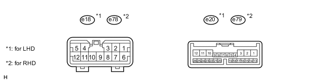
CHECK FRONT POWER SEAT SWITCH RH
-
for LHD:
Disconnect the e18 and e20 switch connectors.
-
for RHD:
Disconnect the e78 and e79 switch connectors.
-
Measure the voltage and resistance according to the value(s) in the table below.
for LHD Terminal No.
(Symbols)
Wiring Color Terminal Description Condition Specified Condition e18-6 (GND) - Body ground W-B - Body ground Ground Always Below 1 Ω e18-7 (+B) - e45-6 (GND) B - W-B Power source Always 11 to 14 V e20-4 (SYSB) - e45-6 (GND) R - W-B Power source Always 11 to 14 V for RHD Terminal No.
(Symbols)
Wiring Color Terminal Description Condition Specified Condition e78-6 (GND) - Body ground W-B - Body ground Ground Always Below 1 Ω e78-7 (+B) - e78-6 (GND) B-R - W-B Power source Always 11 to 14 V e79-4 (SYSB) - e78-6 (GND) B - W-B Power source Always 11 to 14 V -
for LHD:
Reconnect the e18 and e20 switch connectors.
-
for RHD:
Reconnect the e78 and e79 switch connectors.
-
Measure the voltage according to the value(s) in the table below.
for LHD Terminal No.
(Symbols)
Wiring Color Terminal Description Condition Specified Condition e20-12 (SLD+) - e18-6 (GND) B - W-B Sliding motor signal
(forward)
Seat moving forward using sliding switch 11 to 14 V Other Below 1 V e20-11 (SLD-) - e18-6 (GND) R - W-B Sliding motor signal
(rearward)
Seat moving rearward using sliding switch 11 to 14 V Other Below 1 V e20-1 (FUP) - e18-6 (GND) R - W-B Front vertical motor signal
(upward)
Seat cushion front portion rising using front vertical switch 11 to 14 V Other Below 1 V e18-12 (FDWN) - e18-6 (GND) L - W-B Front vertical motor signal
(downward)
Seat cushion front portion lowering using front vertical switch 11 to 14 V Other Below 1 V e20-3 (RCL+) - e18-6 (GND) L - W-B Reclining motor signal
(forward)
Seatback moving forward using reclining switch 11 to 14 V Other Below 1 V e18-3 (RCL-) - e18-6 (GND) B-W - W-B Reclining motor signal
(rearward)
Seatback moving rearward using reclining switch 11 to 14 V Other Below 1 V e18-11 (H+) - e18-6 (GND) W - W-B Headrest motor signal
(upward)
Headrest moving upward using headrest switch 11 to 14 V Other Below 1 V e18-8 (H-) - e18-6 (GND) Y - W-B Headrest motor signal
(downward)
Headrest moving downward using headrest switch 11 to 14 V Other Below 1 V e20-2 (RUP) - e18-6 (GND) B - W-B Lifter motor signal
(upward)
Seat rising using lifter switch 11 to 14 V Other Below 1 V e18-5 (RDWN) - e18-6 (GND) G-B - W-B Lifter motor signal
(downward)
Seat lowering using lifter switch 11 to 14 V Other Below 1 V e18-10 (L+) - e18-6 (GND) R-L - W-B Lumbar motor signal
(forward)
Lumbar switch (forward) ON 11 to 14 V Other Below 1 V e18-1 (L-) - e18-6 (GND) G-Y - W-B Lumbar motor signal
(rearward)
Lumbar switch (rearward) ON 11 to 14 V Other Below 1 V e20-6 (SSLB) - e20-18 (SGND) R - BR Lumbar motor signal Lumbar operation 0 to 8 V e20-8 (PVCC) - e20-18 (SGND) V - BR Position sensor power supply Power seat operation 7.2 to 8.8 V e20-23 (SSRS) - e20-18 (SGND) LG - BR Slide direction position signal Slide operation 0 to 8 V e20-9 (SSRL) - e20-18 (SGND) LG - BR Lifter position signal Lifter operation 0 to 8 V e20-22 (SSRR) - e20-18 (SGND) LG - BR Reclining position signal Reclining operation 0 to 8 V e20-21 (SSRH) - e20-18 (SGND) BE - BR Headrest position signal Headrest operation 0 to 8 V e20-19 (SSFV) - e20-18 (SGND) GR - BR Front vertical direction position signal Front vertical operation 0 to 8 V e20-14 (HRRS) - e18-6 (GND) W - W-B Power seat switch signal Full front switch (forward) ON Below 1 V Other 11 to 14 V e20-15 (HRFS) - e18-6 (GND) R - W-B Power seat switch signal Full front switch (rearward) ON Below 1 V Other 11 to 14 V e20-16 (SLDR) - e18-6 (GND) L - W-B Power seat switch signal Slide switch (rearward) ON Below 1 V Other 11 to 14 V e20-17 (SLDF) - e18-6 (GND) G - W-B Power seat switch signal Slide switch (forward) ON Below 1 V Other 11 to 14 V for RHD Terminal No.
(Symbols)
Wiring Color Terminal Description Condition Specified Condition e79-12 (SLD+) - e78-6 (GND) B - W-B Sliding motor signal
(forward)
Seat moving forward using sliding switch 11 to 14 V Other Below 1 V e79-11 (SLD-) - e78-6 (GND) R - W-B Sliding motor signal
(rearward)
Seat moving rearward using sliding switch 11 to 14 V Other Below 1 V e79-10 (C+) - e78-6 (GND) W - W-B Seat cushion motor signal
(forward)
Seat cushion moving forward using cushion switch 11 to 14 V Other Below 1 V e78-4 (C-) - e78-6 (GND) R-B - W-B Seat cushion motor signal
(rearward)
Seat cushion moving rearward using cushion switch 11 to 14 V Other Below 1 V e79-1 (FRV+) - e78-6 (GND) R - W-B Front vertical motor signal
(upward)
Seat cushion front portion rising using front vertical switch 11 to 14 V Other Below 1 V e78-12 (FRV-) - e78-6 (GND) L - W-B Front vertical motor signal
(downward)
Seat cushion front portion lowering using front vertical switch 11 to 14 V Other Below 1 V e79-3 (RCL+) - e78-6 (GND) L - W-B Reclining motor signal
(forward)
Seatback moving forward using reclining switch 11 to 14 V Other Below 1 V e78-3 (RCL-) - e78-6 (GND) B-W - W-B Reclining motor signal
(rearward)
Seatback moving rearward using reclining switch 11 to 14 V Other Below 1 V e78-11 (H+) - e78-6 (GND) W - W-B Headrest motor signal
(upward)
Headrest moving upward using headrest switch 11 to 14 V Other Below 1 V e78-8 (H-) - e78-6 (GND) Y - W-B Headrest motor signal
(downward)
Headrest moving downward using headrest switch 11 to 14 V Other Below 1 V e79-2 (RRV+) - e78-6 (GND) B - W-B Lifter motor signal
(upward)
Seat rising using lifter switch 11 to 14 V Other Below 1 V e78-5 (RRV-) - e78-6 (GND) G-B - W-B Lifter motor signal
(downward)
Seat lowering using lifter switch 11 to 14 V Other Below 1 V e78-9 (LV+) - e78-6 (GND) R - W-B Lumbar motor signal
(upward)
Lumbar switch (upward) ON 11 to 14 V Other Below 1 V e78-2 (LV-) - e78-6 (GND) L-R - W-B Lumbar motor signal
(downward)
Lumbar switch (downward) ON 11 to 14 V Other Below 1 V e78-10 (L+) - e78-6 (GND) R-L - W-B Lumbar motor signal
(forward)
Lumbar switch (forward) ON 11 to 14 V Other Below 1 V e78-1 (L-) - e78-6 (GND) G-Y - W-B Lumbar motor signal
(rearward)
Lumbar switch (rearward) ON 11 to 14 V Other Below 1 V e79-6 (SSLB) - e78-6 (GND) R - W-B Lumbar motor signal Lumbar operation 0 to 8 V e79-7 (SSLV) - e78-6 (GND) G - W-B Lumbar motor signal Lumbar operation 0 to 8 V e79-8 (PVCC) - e79-18 (SGND) V - BR Position sensor power supply Power seat operation 7.2 to 8.8 V e79-23 (SSRS) - e79-18 (SGND) LG - BR Slide direction position signal Slide operation 0 to 8 V e79-19 (SSFV) - e79-18 (SGND) GR - BR Front vertical direction position signal Front vertical operation 0 to 8 V e79-9 (SSRV) - e79-18 (SGND) LG - BR Lifter position signal Lifter operation 0 to 8 V e79-22 (SSRR) - e79-18 (SGND) LG - BR Reclining position signal Reclining operation 0 to 8 V e79-21 (SSRH) - e79-18 (SGND) BE - BR Headrest position signal Headrest operation 0 to 8 V e79-20 (SSRC) - e79-18 (SGND) Y - BR Seat cushion position signal Seat cushion operation 0 to 8 V e79-15 (DBCL) - e78-6 (GND) Y - W-B Buckle switch signal Power switch off
Driver side seat belt is unfastened
11 to 14 V Power switch off
Driver side seat belt is fastened
Below 1 V e79-16 (DRDC) - e78-6 (GND) W - W-B Buckle switch signal Power switch on (IG)
Driver side seat belt is unfastened
11 to 14 V Power switch on (IG)
Driver side seat belt is fastened
Below 1 V
-
-
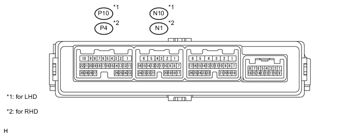
CHECK FRONT DOOR ECU (for Driver Side)
-
for LHD:
-
Disconnect the N10 ECU connector.
-
Measure the resistance and voltage according to the value(s) in the table below.
Terminal No. (Symbols) Wiring Color Terminal Description Condition Specified Condition N10-11 (CPUB) - N10-1 (GND) B - W-B Power source Always 11 to 14 V N10-3 (SIG) - N10-1 (GND) L - W-B Ignition power supply Power switch off Below 1 V Power switch on (IG) 11 to 14 V N10-6 (BDR) - N10-1 (GND) BE - W-B Power source Always 11 to 14 V N10-1 (GND) - Body ground W-B - Body ground Ground Always Below 1 Ω
-
-
for RHD:
-
Disconnect the N1 ECU connector.
-
Measure the resistance and voltage according to the value(s) in the table below.
Terminal No.
(Symbols)
Wiring Color Terminal Description Condition Specified Condition N1-11 (CPUB) - N1-1 (GND) B - W-B Power source Always 11 to 14 V N1-3 (SIG) - N1-1 (GND) L - W-B Ignition power supply Power switch off Below 1 V Power switch on (IG) 11 to 14 V N1-6 (BDR) - N1-1 (GND) BE - W-B Power source Always 11 to 14 V N1-1 (GND) - Body ground W-B - Body ground Ground Always Below 1 Ω
-
-
for LHD:
-
Reconnect the N10 ECU connector.
-
Measure the voltage according to the value(s) in the table below.
Terminal No.
(Symbols)
Wiring Color Terminal Description Condition Specified Condition P10-13 (M1) - P10-29 (MSWE) R - V Memory 1 switch signal Memory 1 switch OFF 11 to 14 V Memory 1 switch ON Below 1 V P10-14 (M2) - P10-29 (MSWE) B - V Memory 2 switch signal Memory 2 switch OFF 11 to 14 V Memory 2 switch ON Below 1 V P10-15 (M3) - P10-29 (MSWE) Y - V Memory 3 switch signal Memory 3 switch OFF 11 to 14 V Memory 3 switch ON Below 1 V P10-16 (MM) - P10-29 (MSWE) BE - V Memory SET switch signal Memory SET switch OFF 11 to 14 V Memory SET switch ON Below 1 V
-
-
for RHD:
-
Reconnect the N1 ECU connector.
-
Measure the voltage according to the value(s) in the table below.
Terminal No.
(Symbols)
Wiring Color Terminal Description Condition Specified Condition P4-13 (M1) - P4-29 (MSWE) R - V Memory 1 switch signal Memory 1 switch OFF 11 to 14 V Memory 1 switch ON Below 1 V P4-14 (M2) - P4-29 (MSWE) B - V Memory 2 switch signal Memory 2 switch OFF 11 to 14 V Memory 2 switch ON Below 1 V P4-15 (M3) - P4-29 (MSWE) Y - V Memory 3 switch signal Memory 3 switch OFF 11 to 14 V Memory 3 switch ON Below 1 V P4-16 (MM) - P4-29 (MSWE) BE - V Memory SET switch signal Memory SET switch OFF 11 to 14 V Memory SET switch ON Below 1 V
-
-
-
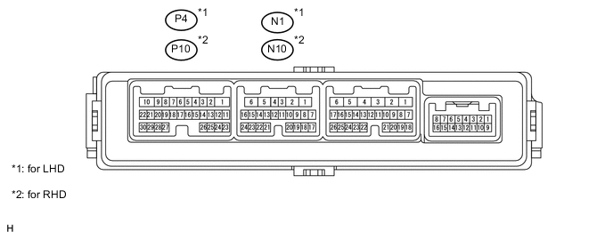
CHECK FRONT DOOR ECU (for Passenger Side)
-
for LHD:
-
Disconnect the N1 ECU connector.
-
Measure the resistance and voltage according to the value(s) in the table below.
Terminal No.
(Symbols)
Wiring Color Terminal Description Condition Specified Condition N1-11 (CPUB) - N1-1 (GND) R - W-B Power source Always 11 to 14 V N1-3 (SIG) - N1-1 (GND) V - W-B Ignition power supply Power switch off Below 1 V Power switch on (IG) 11 to 14 V N1-6 (BDR) - N1-1 (GND) BE - W-B Power source Always 11 to 14 V N1-1 (GND) - Body ground W-B - Body ground Ground Always Below 1 Ω
-
-
for RHD:
-
Disconnect the N10 ECU connector.
-
Measure the resistance and voltage according to the value(s) in the table below.
Terminal No. (Symbols) Wiring Color Terminal Description Condition Specified Condition N10-11 (CPUB) - N10-1 (GND) R - W-B Power source Always 11 to 14 V N10-3 (SIG) - N10-1 (GND) V - W-B Ignition power supply Power switch off Below 1 V Power switch on (IG) 11 to 14 V N10-6 (BDR) - N10-1 (GND) BE - W-B Power source Always 11 to 14 V N10-1 (GND) - Body ground W-B - Body ground Ground Always Below 1 Ω
-
-
for LHD:
-
Reconnect the N1 ECU connector.
-
Measure the voltage according to the value(s) in the table below.
Terminal No.
(Symbols)
Wiring Color Terminal Description Condition Specified Condition P4-13 (M1) - P4-29 (MSWE) R - V Memory 1 switch signal Memory 1 switch OFF 11 to 14 V Memory 1 switch ON Below 1 V P4-14 (M2) - P4-29 (MSWE) B - V Memory 2 switch signal Memory 2 switch OFF 11 to 14 V Memory 2 switch ON Below 1 V P4-15 (M3) - P4-29 (MSWE) Y - V Memory 3 switch signal Memory 3 switch OFF 11 to 14 V Memory 3 switch ON Below 1 V P4-16 (MM) - P4-29 (MSWE) BE - V Memory SET switch signal Memory SET switch OFF 11 to 14 V Memory SET switch ON Below 1 V
-
-
for RHD:
-
Reconnect the N10 ECU connector.
-
Measure the voltage according to the value(s) in the table below.
Terminal No.
(Symbols)
Wiring Color Terminal Description Condition Specified Condition P10-13 (M1) - P10-29 (MSWE) R - V Memory 1 switch signal Memory 1 switch OFF 11 to 14 V Memory 1 switch ON Below 1 V P10-14 (M2) - P10-29 (MSWE) B - V Memory 2 switch signal Memory 2 switch OFF 11 to 14 V Memory 2 switch ON Below 1 V P10-15 (M3) - P10-29 (MSWE) Y - V Memory 3 switch signal Memory 3 switch OFF 11 to 14 V Memory 3 switch ON Below 1 V P10-16 (MM) - P10-29 (MSWE) BE - V Memory SET switch signal Memory SET switch OFF 11 to 14 V Memory SET switch ON Below 1 V
-
-